Quick Summary: A 2-axis digital readout (DRO) is a game-changer for your lathe, offering precise measurement and improved accuracy. It eliminates tedious manual calculations, boosts confidence in your cuts, and is a highly recommended, straightforward upgrade for beginners and experienced machinists alike to achieve better results faster.
It can be tough measuring precisely on a lathe, right? You’re trying to get that diameter just so, or that shoulder to a specific length, and you’re squinting at tiny dial markings. It’s easy to get frustrated, and honestly, it can make even simple jobs feel like a headache. But what if there was a way to make measuring much simpler, more accurate, and less stressful? There is! Adding a 2-axis digital readout to your lathe is one of the most rewarding upgrades you can make. It’s not as complicated as it sounds, and we’re going to walk through exactly why it’s so great and how it can transform your machining. Get ready to say goodbye to measurement guesswork and hello to precision!
Why a 2-Axis DRO is a Lathe Essential Upgrade
As a machinist, I’ve seen firsthand how much a good tool can change the game. For the lathe, that’s definitely a 2-axis digital readout (DRO). If you’re new to machining or even if you’ve been at it for a while, you might be wondering if it’s really worth the investment. Let me tell you, it absolutely is. Think of it as giving your lathe superpowers for accuracy.
The Pain Points of Traditional Measurement
Before we dive into the awesome benefits of a DRO, let’s talk about the challenges you face without one. When you rely on standard dials on your lathe (the cross-slide and compound rest), you’re dealing with a few things:
Guesswork and Small Increments: Those dials have markers, and sometimes they’re tiny. Trying to hit a really specific dimension can feel like threading a needle while wearing mittens. You’re often trying to estimate between the lines, which isn’t ideal for tight tolerances.
Cumulative Error: Every time you turn the handwheel, you’re moving the tool. Over time, a tiny bit of play or wear in the lead screw or gears can add up. This means your dial might say you’ve moved .100 inches, but the tool has only moved .098 inches. This error can be a real headache for precision work.
Mental Math: You need to constantly keep track of where your tool is in relation to your target dimension. Are you at zero? Have you moved .050 inches? Did you bore that hole to .750 inches or .749? It’s a lot to juggle in your head, especially when you’re concentrating on turning or facing.
Tool Changes and Setbacks: If you have to remove a tool, re-zero, or move the carriage for any reason, it’s very easy to lose your exact position. Getting back to your starting point can be a frustrating process of trial and error.
What is a 2-Axis Digital Readout?
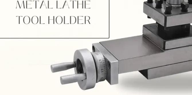
So, what exactly is this magical DRO? Simply put, it’s a display unit connected to sensors (called linear scales) that you attach to the moving parts of your lathe. For a lathe, “2-axis” typically refers to the X-axis (across the bed, controlled by the cross-slide) and the Z-axis (along the bed, controlled by the carriage).
The Display Unit: This is the screen you’ll look at. It shows you the position of your cutting tool in precise, easy-to-read numbers for both the X and Z axes. You can easily zero out the display at any point, switch between inches and millimeters, and sometimes do other helpful calculations.
Linear Scales: These are the “brains” of the measurement. They are long, slim metal strips with incredibly fine magnetic or optical gratings encoded on them. You mount one scale to the stationary part of your lathe (like the bed or saddle) and the other end to the moving part (like the cross-slide or carriage). As the parts move, the scale detects this movement and sends the information to the display unit.
The Transformative Benefits of a DRO
Once you install a 2-axis DRO, you’ll wonder how you ever lived without it. Here’s why it’s such a valuable upgrade:
Unmatched Accuracy: No more guesswork. The DRO shows you the actual position of your tool, not just a mechanical indicator. This means you can hold much tighter tolerances, making your parts fit together perfectly. This is crucial for any project where precision matters, from simple hobby parts to functional machine components.
Reduced Frustration and Error: With clear digital numbers, you can see exactly how much you’ve moved. This significantly reduces the chances of overcutting or undercutting. The mental load of tracking your position is gone, freeing you up to focus on the cutting itself and ensuring a smooth, clean finish.
Easier Setup and Machining: Need to face off .050 inches? Move the tool, read the display. Need to turn a diameter to 1.500 inches? Move the tool, read the display. You can zero the readout at any point – perfect for roughing, then zeroing again to take a final finishing pass. If you need to move away to change a tool or check a dimension and come back, you can simply re-zero to your original starting point.
Improved Efficiency: Because you’re not second-guessing your measurements or making multiple passes to correct errors, you can machine parts faster and more confidently. Less rework means more completed projects.
Enhanced Learning: For beginners, a DRO is an incredible learning tool. It helps you understand machine calibration, the relationship between handwheel turns and actual movement, and the importance of precise positioning. It builds confidence and makes the learning curve much smoother.
Switch Between Units: Most DROs allow you to switch between inches and millimeters with a press of a button, useful if you’re working from plans in different units or collaborating with others.
Choosing the Right 2-Axis DRO System
Not all DRO systems are created equal, so it’s important to pick one that fits your lathe and your needs. There are two main types of DRO systems you’ll commonly encounter for lathes:
Magnetic vs. Optical Scales
This is a key decision and often comes down to budget, environment, and desired precision.
Optical Scales: These are the traditional and generally more accurate type of linear scales. They use a precise optical grating.
Pros: High precision, excellent resolution, usually more durable against minor chips and dust if well-sealed.
Cons: Can be more sensitive to heavy contamination (coolant spray, metal dust buildup if not properly protected), sometimes more expensive.
Typical Resolution: Often 0.0002 inches (5 microns).
Magnetic Scales: These are a more modern and often more affordable option, using magnetic encoded strips.
Pros: Generally more resistant to coolant, oil, and dust contamination. Often can be a more budget-friendly choice.
Cons: May have slightly less inherent accuracy or resolution compared to high-end optical scales, although for most lathe work, they are more than sufficient.
Typical Resolution: Often 0.0005 inches (10 microns) or 0.0002 inches (5 microns).
For most home workshop and hobbyist lathes, both magnetic and optical scales will provide a massive upgrade. Magnetic scales are often a great choice for their robustness in a typical workshop environment.
Key Features to Look For
When shopping for a DRO kit, consider these features:
Scale Length: This is critical. You need scales that are long enough to cover the full travel of your lathe’s cross-slide and carriage. Measure the maximum travel of each axis and ensure the scales you buy are at least that long, preferably a little longer (e.g., if your cross-slide travels 6 inches, get a 6-inch or 7-inch scale). You can often buy scales in standard lengths.
Resolution: This is the smallest increment the DRO can measure and display (e.g., 0.0002″ or 0.0005″). Higher resolution means greater potential accuracy.
Included Mounts and Hardware: Does the kit come with the necessary mounting brackets, screws, and arms to attach the scales to your specific lathe model? Some kits are more universal, while others might specify lathe types.
Display Unit Features:
Zeroing: Ability to zero out the display at any position on either axis.
Absolute/Relative Modes: Ability to switch between absolute (position from a fixed origin) and relative (distance moved from the last zero) measurements.
Presetting: Ability to input a target value and have the DRO count down to it.
ABS/INC (Absolute/Incremental): This is a common feature, allowing you to switch between tracking absolute position and measuring incremental movement.
Units Conversion: Easy switching between inches and millimeters.
Brand Reputation and Support: Look for well-known brands in the DRO market. Good customer support can be invaluable if you run into installation or operational questions. Many kits are imported, but researching reviews can help.
Common Lathe DRO Kits
Many manufacturers offer 2-axis and 3-axis DRO kits. For a lathe, a 2-axis system (X and Z) is the standard and most beneficial. Some advanced setups might consider a 3rd axis for quill travel on a mill-drill, but for a standalone lathe, 2-axis is the way to go.
Popular brands often found in workshops include brands known for their machining accessories. You’ll see kits that bundle a display console with two scalable lengths and all the necessary arms and mounting hardware. It’s worth browsing specialized machining supply stores online or looking at what your lathe manufacturer might recommend if they offer upgrades.
Installing a 2-Axis DRO on Your Lathe: A Step-by-Step Guide
Installing a DRO is a very doable project for the home machinist. It requires patience, careful measurement, and a bit of fabrication, but the result is incredibly rewarding. Always prioritize safety – disconnect power to the lathe before you begin any work!
Tools and Materials You’ll Need
Before you start, gather these items:
Your 2-Axis DRO Kit: Make sure it includes scales, display, and mounting hardware.
Basic Hand Tools: Wrenches, screwdrivers, Allen keys.
Measuring Tools: Calipers (digital or dial), ruler, measuring tape.
Drill and Drill Bits: For creating mounting holes.
Tap and Tap Handle: To thread holes for mounting screws if needed.
Files: For deburring and minor fitting.
Center Punch: To mark hole locations accurately.
Cutting Fluid: To help with drilling and tapping.
Dremel or Grinding Tool (Optional): For minor adjustments to brackets.
Safety Glasses: Absolutely essential!
Shop Rags: For cleanup.
Step-by-Step Installation
The exact steps will vary depending on your lathe model and the specific DRO kit, but here’s a general guide:
Step 1: Plan Your Scale Placement
This is the most critical step. You need to mount the scales so that their movement precisely matches the movement of your lathe’s axes, without any binding or interference.
X-Axis (Cross-Slide): The scale will typically be mounted to the bed or apron and the cross-slide or tool post housing. You want the scale running parallel to the cross-slide ways. Ensure the scale reader head is positioned to read the scale along its entire length of travel.
Z-Axis (Carriage): The scale will usually be mounted to the headstock end of the bed and the carriage. The scale should run parallel to the bed ways. Again, check that the reader head has full travel.
Step 2: Mount the X-Axis Scale
1. Positioning: Carefully place the X-axis scale along the side of your lathe bed or apron where it will move with the cross-slide. Use clamps or tape to temporarily hold it in place.
2. Alignment: Ensure the scale is perfectly parallel to the ways the cross-slide moves on. Use calipers or a dial indicator to check alignment. A slight misalignment can cause binding and inaccuracy.
3. Marking Holes: Once aligned, carefully mark the desired mounting hole locations on the lathe bed or apron. Use a center punch to create divots for accurate drilling.
4. Drilling and Tapping: Remove the scale. Drill pilot holes at your marked locations. If tapping threads directly into the lathe casting, use the appropriate size drill bit and tap, drilling to the correct depth. Always use cutting fluid. Clean out the chips thoroughly.
5. Mounting: Re-position the scale and secure it with the provided mounting screws. Hand-tighten for now.
6. Mount the Reader Head: Attach the reader head to the moving part of the cross-slide, ensuring it aligns with the scale. The DRO kit should provide brackets and hardware for this.
Step 3: Mount the Z-Axis Scale
1. Positioning: Repeat the process for the Z-axis scale, typically mounted along the bed. Ensure it runs perfectly parallel to the carriage travel.
2. Alignment: Check for parallelism with the bed ways. Small deviations here are critical.
3. Marking, Drilling, Tapping, and Mounting: Similar to the X-axis, mark, punch, drill, tap, and mount the Z-axis scale.
4. Mount the Reader Head: Attach the Z-axis reader head to the carriage, ensuring it tracks the scale smoothly.
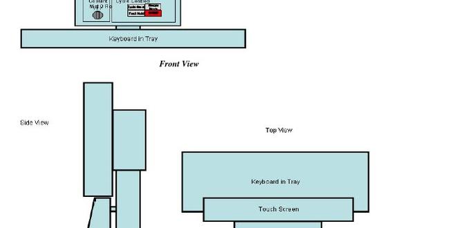
Step 4: Mount the Display Unit
1. Location: Find a convenient place on your lathe for the display unit. Common spots are on the headstock housing, the base of the lathe, or a custom-made bracket. It should be easily visible and accessible while operating the lathe.
2. Secure: Mount the display unit using its bracket and screws.
Step 5: Route and Connect Cables
1. Cable Management: This is very important for safety and longevity. Route any cables from the reader heads to the display unit, keeping them away from moving parts, chuck, and any hot surfaces or chip streams. Flexible conduit or cable ties are your friends here. Consider how the cables will flex as the axes move.
2. Connections: Connect the reader head cables to the appropriate ports on the display unit. Most DROs have clearly labeled ports for X and Z axes.
Step 6: Initial Power-Up and Testing
1. Power On: Before plugging into mains power, double-check all connections. Then, plug in the display unit and turn it on.
2. Zero Axis: The display should show zeros for both axes, or some initial reading. Press the “Zero” button for each axis while the reader heads are stationary.
3. Test Movement: Slowly move the cross-slide through its entire travel. Observe the X-axis reading on the display. Does it increase/decrease smoothly? Does it accurately reflect the distance moved? Repeat for the Z-axis.
4. Check for Binding: While testing, feel for any stiffness or binding in the movement. If you find any, re-check your scale alignment and mounting. Even a loose screw can cause issues.
5. Measure a Known Distance: Use your calipers to measure a specific travel, say moving the cross-slide exactly 1 inch. Then, move the cross-slide that distance and see if the DRO also reads 1 inch (or very close to it, within its rated tolerance).
Step 7: Fine-Tuning and Final Touches
Tighten Everything: Once you’re satisfied with the alignment and movement, securely tighten all mounting screws.
Cable Management (Final): Neatly secure all cables using zip ties or conduit mounts. Ensure they have enough slack to move freely but are not a snagging hazard.
Clean Up: Remove any swarf or debris from the installation process.
Important Note on Lathe Types:
Benchtop Lathes: Installation is generally straightforward. These lathes often have accessible mounting surfaces.
Larger Floor-Standing Lathes: These may require custom brackets or more involved mounting solutions. Always refer to your lathe’s manual and consider consulting with experienced machinists if you’re unsure.
DRO Calibration and Maintenance
Once installed, DROs require very little maintenance.
Cleaning: Keep the scales clean. A soft cloth and a bit of isopropyl alcohol is usually sufficient for cleaning the scale housings. Avoid harsh solvents. If your scale has bellows or seals, check them periodically.
Checking Alignment: Occasionally, especially after a significant operation or if you notice erratic readings, re-check the alignment and mounting of your scales.
Battery (for some models): Some battery-powered DROs might need battery replacements.
Resources for Installation
For extremely specific guidance, it’s often best to:
Consult the DRO Manufacturer’s Manual: Every kit comes with detailed instructions.
Watch Online Videos: Many machinists document their DRO installations on platforms like YouTube. Search for your lathe model and “DRO install” to find helpful visual guides.
Refer to Machining Forums: Websites like Practical Machinist have vast archives and active communities where you can ask specific questions.
Understanding Your DRO Display: Functions and Features
Once your DRO is installed and powered up, you’ll want to get familiar with its display unit. These consoles are packed with useful features that make machining much more efficient and precise.
Essential Functions at a Glance
Here’s a breakdown of common buttons and readouts you’ll find on most DRO units:
| Button/Feature | Description | How It Helps You |
| :—————–