Unlock perfect Delrin machining with a 5/8 inch carbide end mill. This guide reveals ideal feeds and speeds, banishing chatter, melting, and tool wear so you can achieve clean cuts and smooth finishes on your projects with confidence.
Hey there, fellow makers! Daniel Bates here from Lathe Hub. Ever stared at a block of Delrin, ready to cut, only to get lost in the numbers for feeds and speeds? You’re not alone. Getting the right settings for your 5/8 inch carbide end mill can feel like a puzzle, especially with plastics like Delrin. Too fast, and you get melting. Too slow, and you get chattering. It’s frustrating when your parts don’t turn out as clean as you imagined. But don’t worry! Today, we’re going to demystify the perfect feed and speed combination. We’ll break it all down so you can get those beautiful, crisp cuts on Delrin every single time. Ready to make your Delrin projects shine?
Understanding Delrin and Why Feeds & Speeds Matter
Delrin, also known by its generic name acetal, is a fantastic engineering thermoplastic. It’s strong, stiff, and has excellent low friction properties, making it a favorite for gears, bearings, and intricate parts. It’s often called the “poor man’s metal” because it machines so well and can replace metal in many applications. However, Delrin can be a bit finicky when it comes to machining. It’s prone to melting if too much heat is generated, and it loves to chip if the cutting forces are too high.
This is where the concept of “feeds and speeds” becomes critical. Simply put, these are the two main controllers of how your end mill interacts with the material:
- Spindle Speed (RPM): This is how fast the cutting tool (your end mill) spins. Measured in revolutions per minute (RPM).
- Feed Rate: This is how fast the tool moves through the material. Measured in inches per minute (ipm) or millimeters per minute (mm/min).
Finding the sweet spot for these two is essential for several reasons:
- Tool Life: Incorrect speeds can quickly overheat and wear down your carbide end mill, making it dull and less effective.
- Surface Finish: The right combination results in clean, smooth cuts instead of rough, stringy, or melted surfaces.
- Machine Performance: Proper settings reduce strain on your machine’s motor and spindle, preventing damage and ensuring consistent operation.
- Chip Formation: Good feeds and speeds help create small, manageable chips that are easily evacuated, further reducing heat buildup.
For a 5/8 inch carbide end mill cutting Delrin, precision is key. We’re aiming for a cut that removes material efficiently without generating excessive heat or force.
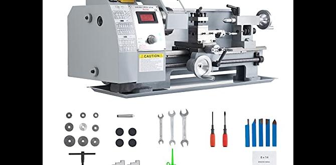
Why a 5/8 Inch Carbide End Mill?
Carbide end mills are generally preferred for machining plastics like Delrin. They are much harder and more heat-resistant than High-Speed Steel (HSS) tools. This is crucial because Delrin can generate heat quickly. A carbide tool can maintain its sharpness and cutting ability at higher temperatures.
Now, why specifically a 5/8 inch end mill? This size offers a good balance. It’s large enough to remove material efficiently for many common projects, and it’s sturdy enough to handle moderate cutting forces without flexing too much. It’s a versatile workhorse in many home and professional workshops. For slotting, profiling, or facing operations on Delrin, getting the feeds and speeds right for this common size is a skill worth mastering.
Essential Variables for Delrin Machining
When we talk about “genius Delrin speeds,” we’re not just pulling numbers out of a hat. Several factors influence the optimal settings for your 5/8 inch carbide end mill:
- Number of Flutes: This is how many cutting edges your end mill has. For plastics like Delrin, fewer flutes (2 or 3) are often better. They create larger chip gullets, allowing chips to escape more easily and reducing the risk of recutting chips, which causes heat. More flutes (4 or more) can sometimes work with careful settings, especially for finishing passes.
- Material Type: While we’re focusing on Delrin (acetal), there are different grades. However, for general purposes, standard acetal is what most hobbyists encounter.
- Coolant/Lubrication: Delrin machining can benefit from a little help to keep things cool. Compressed air is a common and effective choice for plastics. It blows chips away and cools the cutting zone. Sometimes, a light mist coolant or even a cutting lubricant specifically designed for plastics can be used, but be cautious; too much can sometimes lead to chip packing.
- Machine Rigidity: A sturdy, rigid machine will handle higher cutting forces and speeds better than a flimsy one. A less rigid machine might require slower speeds and lighter cuts to avoid vibration.
- Depth of Cut (DOC) and Width of Cut (WOC): How deep and how wide each pass is. Shallower cuts generally allow for higher feed rates and spindle speeds, and vice versa.
- Chip Load: This is the thickness of the material being removed by each cutting edge per revolution. It’s closely related to feed rate and RPM. A target chip load helps ensure efficient material removal without overwhelming the cutter or the machine.
Understanding these variables helps you fine-tune the settings provided in the next section.
Calculating and Finding Ideal Feeds & Speeds for Delrin – The Sweet Spot!

Let’s get to the heart of it. For a 5/8 inch (0.625 inch) carbide end mill cutting Delrin, we’re looking for settings that promote efficient material removal, create good chips, and keep temperatures down. We’ll primarily focus on a 2-flute carbide end mill, as it’s a very common and effective choice for Delrin.
Understanding Chip Load
Chip load is a fundamental concept. It’s the amount of material each tooth of the end mill removes in one revolution. A good chip load prevents melting and excessive wear. For a plastic like Delrin, a general starting point for chip load with a 5/8 inch end mill might range from 0.003 to 0.007 inches per tooth (ipt). Let’s aim for the middle ground for our initial calculations.
Key Formulas
Here are the basic formulas to help us:
- Surface Speed (SFM): This is the speed at which the cutting edge moves along the material. Carbide manufacturers provide recommended SFM for their tools and materials. For Delrin with carbide, a good starting range is often between 300-600 SFM. Let’s use 400 SFM as a baseline.
- Spindle Speed (RPM): Formula: `RPM = (SFM 12) / (π Diameter)`
- Feed Rate (IPM): Formula: `Feed Rate = RPM Number of Flutes Chip Load`
Calculating for a 5/8 Inch (0.625″) 2-Flute Carbide End Mill
Let’s plug in some numbers:
- Diameter (D): 0.625 inches
- Number of Flutes (N): 2
- Target Surface Speed (SFM): 400 SFM
- Target Chip Load (ipt): Let’s start with 0.005 inches per tooth – a good middle ground for plastics.
1. Calculate Spindle Speed (RPM):
`RPM = (400 SFM 12) / (3.14159 0.625 inches)`
`RPM = 4800 / 1.9635`
`RPM ≈ 2445 RPM`
So, a good starting point for spindle speed is around 2400-2500 RPM.
2. Calculate Feed Rate (IPM):
`Feed Rate = 2445 RPM 2 Flutes 0.005 ipt`
`Feed Rate = 2445 0.01`
`Feed Rate ≈ 24.45 IPM`
This gives us a good starting feed rate of around 24-25 IPM.
Recommended Starting Feeds and Speeds Table
This table provides a solid starting point. Always remember these are guidelines, and you might need to adjust based on your specific setup. For best results, especially when learning, use a CNC machine that allows you to easily adjust these parameters on the fly or set them precisely.
| Parameter | Value (Approximate) | Notes |
|---|---|---|
| End Mill Diameter | 5/8 inch (0.625″) | Carbide, 2 Flutes |
| Material | Delrin (Acetal) | Standard grades |
| Surface Speed (SFM) | 300 – 600 SFM | Aiming for ~400 SFM for calculation |
| Chip Load per Tooth (ipt) | 0.003 – 0.007 inches | Start around 0.005 ipt |
| Spindle Speed (RPM) | 2100 – 3300 RPM | Calculated target: ~2450 RPM for 400 SFM |
| Feed Rate (IPM) | 18 – 45 IPM | Calculated target: ~24.5 IPM at 0.005 ipt |
| Depth of Cut (DOC) | 0.050″ – 0.250″ | Lower DOC for finishing, higher for roughing. Start conservative. |
| Width of Cut (WOC) | 25% – 50% of diameter (0.156″ – 0.312″) | Climb milling is often preferred. |
| Cooling | Compressed Air | Essential for chip evacuation and cooling. |
Adjusting for Different Conditions
If you experience melting or chip welding:
- Decrease the Chip Load: Reduce the feed rate or increase the RPM slightly. This makes each bite smaller, generating less heat per pass.
- Increase Air Blast: More focused air can dramatically help.
- Reduce Depth of Cut: Take lighter passes.
If you experience chatter or vibration:
- Increase Chip Load: Speed up the feed rate slightly or decrease RPM. A more aggressive cut can sometimes grab the material better and reduce vibration.
- Reduce Depth of Cut: Take lighter passes.
- Reduce Width of Cut: For slotting, especially, a narrower cut can sometimes be more stable.
- Ensure Tool is Sharp: A dull tool will chatter.
- Check Machine Rigidity: Ensure all gibs are tight and there’s no play in the machine.
For Finishing Passes:
For a pristine surface finish, you might employ:
- Lower chip load (e.g., 0.002 – 0.003 ipt)
- Higher spindle speed (staying within carbide limits)
- Shallower depth of cut (e.g., 0.010″ – 0.020″)
- Full width of cut if not slotting
This leads to a smoother, almost polished surface.
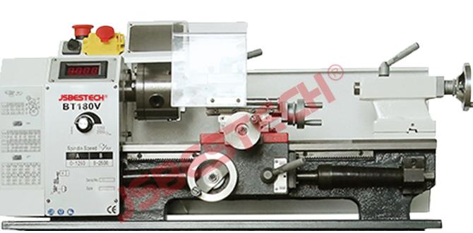
CNC vs. Manual Machining
The settings above are most directly applicable to CNC machines where you can precisely set and adjust RPM and IPM. On a manual machine (like a Bridgeport or similar milling machine), setting feeds and speeds involves more feel and experience. You’ll be relying on:
- Spindle Dial: Setting the desired RPM.
- Handwheel Feel: Gradually feeding the tool into the material and listening and feeling for the right cutting sound and resistance. You’ll want to hear a consistent, light “shaving” sound, not a harsh tearing or grinding.
- Visual Cues: Watching the chips come off – they should be small, clean curls, not long strings or powdery dust.
- Compressed Air: Crucial for flushing chips away.
Regardless of machine type, always start conservatively and gradually increase your cutting parameters until you find the optimal balance for your specific setup.
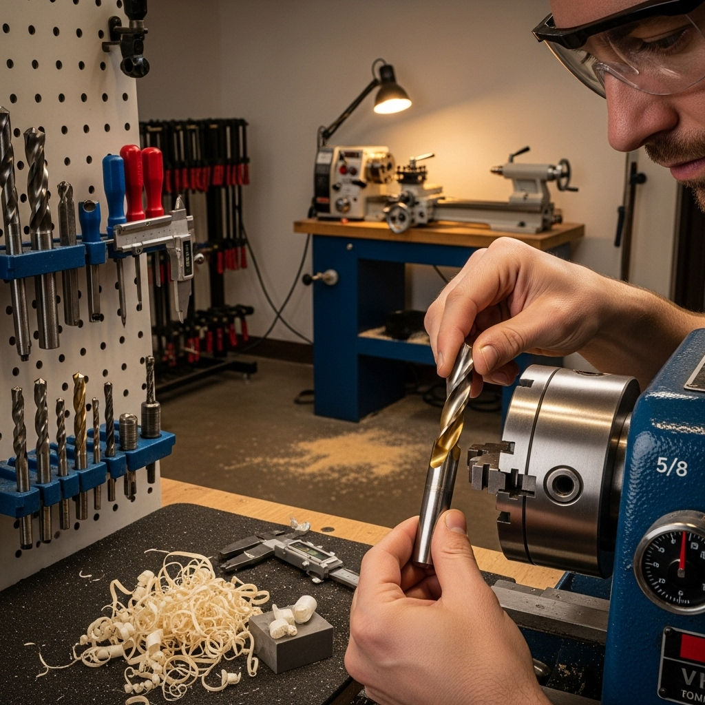
Practical Tips for Machining Delrin
Beyond just feeds and speeds, a few practical tips can make your Delrin machining experience much smoother:
Workholding:
- Delrin is prone to deforming under pressure, especially when heated. Use ample workholding like clamps or a vise, distributing the clamping force as widely as possible.
- Avoid overtightening.
- Consider using soft jaws if clamping directly on finished surfaces.
Chip Evacuation:
- As mentioned, compressed air is your best friend. A blast nozzle directed at the cutting zone can make a huge difference.
- Avoid plunging with the end mill unless absolutely necessary, as this creates a lot of heat in one spot. Use a helical or ramping toolpath if possible.
- Keep your work area clean.
Tooling Considerations:
- Sharpness is Key: Dull tools are the enemy of smooth plastic machining. Use sharp, high-quality carbide end mills.
- Coating: For plastics, uncoated carbide or a TiCN coating can perform well. Avoid coatings that can build up material.
- Single vs. Double vs. Multiple Flutes: While we emphasized 2-flute, a 3-flute can work for Delrin if you maintain a good chip load. For 3-flutes, you’d adjust the feed rate calculation: e.g., at 2400 RPM, 0.005 ipt, a 3-flute would be 2400 3 * 0.005 = 36 IPM. 4-flutes are generally less forgiving with Delrin due to reduced chip clearance.
Heat Management:
- Delrin softens significantly when warm. If the part feels hot to the touch, you’re generating too much heat. Back off parameters or increase cooling.
- Allow the part to cool between passes if necessary, especially for intricate or thin-walled sections.
Learning Resources:
For more in-depth information on machining principles, especially relating to CNC, resources from organizations like the National Institute of Standards and Technology (NIST) can be incredibly valuable. Their work on accuracy and best practices in manufacturing, though often highly technical, underpins many of these machining concepts. You can often find useful papers and databases through academic libraries or directly via their website, looking for terms like “machining data” or “metal cutting.”
Also, reputable tool manufacturers like OSG or Harvey Tool often provide downloadable feeds and speeds charts for their specific tools and various materials, which are excellent references.
Troubleshooting Common Delrin Machining Issues

Let’s cover some specific problems you might encounter and how to fix them, relating back to our 5/8 inch carbide end mill and Delrin.
Issue 1: Melting, Gummy Chips, and Poor Surface Finish
Cause: Too much heat generation. This can be from:
- Spindle RPM too high for the feed rate.
- Chip load too small, causing rubbing instead of cutting.
- Depth of Cut too large.
- Insufficient cooling/chip evacuation.
- Using a tool with too many flutes (low chip clearance).
Solution:
- Reduce Spindle Speed: Lower the RPM.
- Increase Feed Rate: This increases the chip load, creating a more substantial chip that carries heat away better.
- Increase Chip Load (directly): If your machine allows, aim for