Carbide End Mill 1/8 Inch for Cast Iron: Achieving a Mirror Finish is Easier Than You Think!
Get a super smooth, mirror-like finish on cast iron using a 1/8 inch carbide end mill. This guide breaks down the setup, speeds, feeds, and tips to make it simple and reliable, even for beginners.
Working with cast iron can feel a bit intimidating, especially when you’re aiming for that perfect, shiny finish. Many beginners struggle to get a clean cut without chatter or a rough surface. Finding the right tools and knowing how to use them makes all the difference. Don’t worry, this guide will walk you through exactly how to use a 1/8 inch carbide end mill to achieve a proven, beautiful finish on cast iron. We’ll cover everything you need to know, step-by-step, so you can tackle your projects with confidence. Let’s dive in!
Understanding Your 1/8 Inch Carbide End Mill for Cast Iron
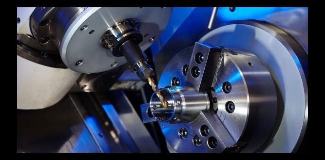
A 1/8 inch carbide end mill is a fantastic tool, but using it effectively on cast iron requires understanding its strengths and how it interacts with this material. Cast iron is brittle yet surprisingly abrasive. Carbide is hard and can withstand the heat generated, making it a good choice. However, the small diameter of a 1/8 inch end mill means it’s quite delicate and can easily break if pushed too hard or incorrectly.
When we talk about a “proven cast iron finish,” we’re aiming for a surface that is not only smooth to the touch but also has a reflective quality, almost like a mirror. This isn’t just about aesthetics; a good finish can indicate a precise and well-executed machining operation. For a 1/8 inch end mill, achieving this level of finish usually involves light passes, appropriate speeds and feeds, and a bit of patience.
Why Carbide for Cast Iron?
- Hardness: Carbide is much harder than High-Speed Steel (HSS), which is crucial for cutting abrasive materials like cast iron.
- Heat Resistance: It can withstand higher cutting temperatures without losing its cutting edge, essential for productive machining.
- Edge Retention: Carbide tools hold their sharp edge longer, providing consistent results for a mirror finish.
The Importance of a 1/8 Inch Diameter
A 1/8 inch end mill is considered a small diameter tool. This has its advantages and disadvantages. For intricate details or small workspaces, it’s ideal. However, on a milling machine, small end mills have shallower depth-of-cut capabilities and are more prone to deflection or breakage due to their small cross-section. This means we have to be extra careful with our cutting parameters.
For achieving a mirror finish, smaller diameter mills can sometimes excel because they can take very light, skimming passes. These light passes minimize the forces acting on the tool and the workpiece, leading to a smoother surface. We’ll focus on strategies that leverage this characteristic.
Essential Tools and Setup for a Mirror Finish
Before you even think about turning on the mill, having the right setup is crucial. This isn’t just about the end mill itself, but the entire ecosystem that supports its operation. For a beginner, a solid setup inspires confidence and reduces the chances of errors.
Your Milling Machine Checklist
Ensure your milling machine is in good working order. This includes:
- Rigidity: The machine should be rigid. Any play in the ways or spindle will translate into poor surface finish and potentially broken tools.
- Spindle Runout: Check your spindle for runout. Excessive runout will cause uneven cutting and a rough finish. A dial indicator is your friend here. Aim for less than 0.0005″ runout.
- Coolant/Lubrication: While dry machining is possible with carbide on cast iron, a light mist of coolant or a suitable cutting fluid can greatly improve surface finish, reduce heat, and extend tool life.
Workholding: The Foundation of Your Cut
Secure workholding is non-negotiable. The cast iron workpiece must be clamped firmly to prevent any movement during the machining process. For a mirror finish, even a tiny bit of vibration from a loose workpiece can ruin your efforts.
- Vise: A solid milling vise is the most common method. Ensure the vise jaws are clean and provide good contact.
- Clamps: If clamping directly to a table, use appropriate clamps and ensure they don’t interfere with the toolpath.
The Right 1/8 Inch Carbide End Mill
Not all 1/8 inch carbide end mills are created equal. For cast iron, look for:
- Number of Flutes: For cast iron, 2-flute or 4-flute end mills are common. 2-flute mills generally offer better chip clearance, which is important for cast iron dust. 4-flute mills can sometimes offer a smoother finish due to more cutting edges engaging the material. For a mirror finish and delicate work with a 1/8″ mill, a high-quality 2-flute end mill specifically designed for cast iron or general aluminum/non-ferrous work can perform exceptionally well by allowing good chip evacuation.
- Coating: Uncoated carbide is often preferred for cast iron as coatings can sometimes load up with the abrasive material. However, some specialized coatings might offer benefits. For simplicity and reliability, uncoated is a safe bet.
- Material: Ensure it’s solid carbide.
- Geometry: Standard geometry is usually fine, but corner radius can sometimes help with stability and finish. For this guide, we’ll assume a standard square end mill.
A “standard length” end mill is generally suitable, but avoid “extra length” tools for small diameters like 1/8 inch as they are more prone to deflection.
Essential Accessories
- Tool Holder: Use a good quality collet chuck or end mill holder that runs true. A Shrink Fit holder offers the best concentricity if available.
- Dial Indicator: For checking spindle runout and tramming.
- Calipers/Micrometer: For accurate measurements.
- Safety Glasses and Face Shield: Absolutely critical.
- Dust Collection: You’ll be generating fine cast iron dust, which is hazardous.
Step-by-Step Guide: Machining Cast Iron with a 1/8 Inch Carbide End Mill
Now that your setup is ready, let’s get to the actual machining. The key to a great finish, especially with a small tool on a tough material like cast iron, is to take light, controlled cuts. This is where precision and patience pay off. Remember, we’re aiming for a mirror finish, which means we’re likely doing a finishing pass rather than a heavy roughing operation.
Step 1: Setting Up the Machine and Workpiece
- Tram the Spindle: Ensure your spindle is perfectly perpendicular to the milling table (trammed). This is crucial for a consistent finish.
- Secure the Workpiece: Clamp your cast iron workpiece firmly in the vise or using toe clamps. Make sure it’s not going anywhere.
- Install the End Mill: Insert the 1/8 inch carbide end mill into a clean collet or end mill holder and tighten securely. Ensure your tool holder is seated properly in the spindle.
- Deburr Edges: If the workpiece has sharp edges from prior operations, deburr them slightly. This prevents the end mill from snagging.
Step 2: Establishing Zero and Tool Offset
- Locate X and Y Zero: Using your preferred method (e.g., edge finder, probe, or sweep), establish your X and Y zero points on the workpiece.
- Set Z Zero: Carefully bring the tip of the end mill down to the top surface of the casting. You can use a piece of paper to feel for contact or an edge finder to find the center of a bore, then set Z zero. Double-check this.
Step 3: Determining Speeds and Feeds
This is perhaps the most critical part for achieving a good finish. For a 1/8 inch carbide end mill on cast iron, we need to use conservative, yet effective, parameters. The goal is to cut cleanly without overloading the tool or the machine.
Surface Speed (SFM) and Spindle Speed (RPM)
A good starting point for coated carbide in cast iron is around 200-300 SFM (Surface Feet per Minute). For uncoated carbide, a bit lower is often safer, around 200-250 SFM. Let’s aim for around 200 SFM for a conservative start, adaptable to your specific machine’s precision.
The formula to calculate spindle speed (RPM) is:
RPM = (SFM × 3.82) / Diameter (inches)
For a 1/8 inch (0.125 inch) diameter end mill and 200 SFM:
RPM = (200 × 3.82) / 0.125 = 764 / 0.125 = 6112 RPM
This is a theoretical speed. Your machine’s actual maximum RPM and stability at that speed are key. If your machine can’t reach this or is unstable, you’ll need to adjust your SFM down.
Chip Load and Feed Rate (IPM)
Chip load is the thickness of the chip that each cutting edge of the end mill removes. For small end mills and finishing passes, you want a very light chip load to promote a good finish and avoid tool breakage.
A typical starting chip load for a 1/8 inch carbide end mill in cast iron for finishing might be:
- 2-flute end mill: 0.001″ – 0.002″ chip load per tooth
- 4-flute end mill: 0.0005″ – 0.001″ chip load per tooth
Let’s use 0.0015″ chip load per tooth for our 2-flute example.
The formula for feed rate (IPM – Inches Per Minute) is:
IPM = Chip Load per Tooth × Number of Flutes × Spindle RPM
Using our calculated 6112 RPM and 0.0015″ chip load for a 2-flute mill:
IPM = 0.0015″ × 2 × 6112 RPM = 18.34 IPM
This is a very light feed rate, essential for a mirror finish. You might be able to push this slightly higher depending on the rigidity of your setup and the quality of the end mill.
Depth of Cut and Stepover
For a mirror finish, you’ll typically be performing a finishing pass. This means very shallow depths of cut and a small radial stepover.
- Axial Depth of Cut (DOC): For finishing, aim for a very shallow DOC, often as little as 0.010″ to 0.020″. You might even do a “skim” pass with only 0.005″ or less removed.
- Radial Stepover: This is how much the tool moves sideways on each pass. For a smooth finish, a larger stepover is often acceptable because the tool is taking a light axial cut. Aim for 50-75% of the tool diameter for a general finish. For a mirror finish on a flat surface, a stepover of 0.050″ to 0.075″ is a good starting point with a 1/8″ mill. If you’re profiling a part, a smaller stepover (e.g., 10-20% of tool diameter) might be needed for corner quality.
| Parameter | Recommended Value (1/8″ Carbide, Cast Iron Finish) | Notes |
|---|---|---|
| Surface Speed (SFM) | 200 – 250 | For uncoated bright finish carbide. Adjust based on coolant use. |
| Spindle Speed (RPM) | ~6,100 RPM (at 200 SFM) | (Calculated: (SFM 3.82) / Diameter) – Verify your machine’s capability. |
| Chip Load per Tooth | 0.001″ – 0.002″ (2-flute) 0.0005″ – 0.001″ (4-flute) |
Start conservative to avoid chatter and breakage. |
| Feed Rate (IPM) | ~12 – 25 IPM | (Calculated: Chip Load Flutes * RPM) – Adjust for smooth cutting. |
| Axial Depth of Cut (DOC) | 0.005″ – 0.020″ | Shallow for finishing. |
| Radial Stepover | 0.050″ – 0.100″ (for surfacing) 0.012″ – 0.025″ (for profiling) |
Affects surface finish quality and time. |
Step 4: Executing the Cut
- Apply Coolant/Lubrication: If using, turn on your coolant mist or apply cutting fluid. This is highly recommended for cast iron.
- Initiate the Cut: Start the spindle at the calculated RPM. Engage the feed rate gradually.
- Plunge Carefully: If plunging into the material, do so at a reduced feed rate or use a helical or ramping entry if your CAM software supports it and the end mill is designed for it. For a 1/8″ mill, direct plunging can be risky.
- Make Your Passes: Follow your programmed toolpath. Listen to the cut. A smooth, consistent sound is what you want. If you hear chattering or grinding, stop immediately and check your parameters or setup.
- Finishing Pass: For the absolute best mirror finish, often a final “skim” pass is performed with a very shallow DOC (0.005″ or less) and a slightly slower feed rate (e.g., halve the feed rate). This pass cleans up any minor imperfections from the previous pass.
A good resource for understanding cutting parameters and tool selection is the Sandvik Coromant Machining Calculator or similar manufacturer resources, though they can be quite technical. For beginners, following established guidelines for similar operations on cast iron is a safe bet.
Step 5: Inspection and Refinement
- Clean the Part: After the final pass, clear away the swarf and coolant.
- Inspect the Finish: Examine the surface under good light. Look for smoothness, reflectivity, and absence of tool marks.
- Adjust as Needed: If the finish isn’t quite where you want it, consider a slightly slower feed rate, a shallower depth of cut for the final pass, or a different coolant. Sometimes, simply cleaning the part and running the finishing pass again can improve results.
Common Issues and How to Solve Them
Even with the best intentions, you might run into problems. Here’s a quick rundown of common issues when milling cast iron with a small end mill and how to address them.
Issue: Chatter or Vibration
- Cause: Tool flex, insufficient rigidity, incorrect speeds/feeds, dull tool, workpiece moving.
- Solution:
- Reduce depth of cut and/or feed rate.
- Ensure workpiece is clamped very securely.
- Increase spindle speed slightly (if possible) to enter the chip load faster, or decrease it to avoid resonant frequencies. Experimentation is key.
- Use a shorter, more rigid tool holder.
- Check for spindle runout or Z-axis backlash.
- Ensure the end mill is sharp and not chipped.
Issue: Poor Surface Finish (Rough, Scalloped)
- Cause: Incorrect stepover percentage, excessive depth of cut, tool wear, machine backlash, spindle runout.
- Solution:
- Reduce axial depth of cut for the finishing pass.
- Try a smaller radial stepover for finer scallops (though this increases machining time).
- Ensure your Z-axis is moving precisely and not lagging.
-