Carbide end mills, specifically 1/8 inch, are excellent for dry cutting FR4 without melting or chipping, offering precision and durability for your PCB projects.
Working with Printed Circuit Boards (PCBs) can sometimes feel intricate, especially when you’re just starting. One common challenge is cutting out PCBs from larger sheets without damaging the delicate FR4 material. Using the wrong tools can lead to frustrating errors like melted edges, chipped traces, or even a broken bit. But don’t worry! With the right approach and the correct information, you can achieve clean, precise cuts every time. This guide will walk you through using a 1/8 inch carbide end mill for dry cutting FR4. We’ll cover everything you need to know to get perfect results, making your PCB projects smoother and more professional.
Understanding the 1/8 Inch Carbide End Mill for FR4 Dry Cutting
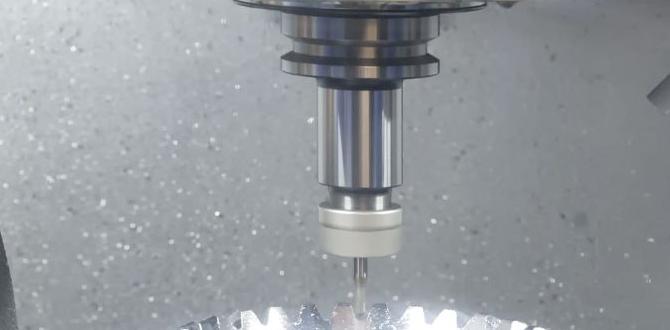
When you’re getting into CNC machining for electronics or model making, the 1/8 inch (or sometimes called 3mm or 3.175mm, depending on the shank size in metric) carbide end mill is a bit of a star player. Specifically, when we talk about cutting FR4 material, which is the common fiberglass epoxy laminate used for most PCBs, dry cutting with a sharp carbide bit is often the preferred method for hobbyists and even some professional shops wanting to avoid messy coolants.
Why carbide? Carbide is incredibly hard and can withstand the heat generated from friction when cutting. FR4, being a fiberglass composite, can be abrasive and generate a surprising amount of heat when machined. A standard HSS (High-Speed Steel) end mill might dull or even melt under these conditions. Carbide’s hardness keeps it sharp for longer and resists the heat much better.
And why 1/8 inch? This size is fantastic for a few reasons, especially for PCB work:
Detail and Precision: A 1/8 inch (3.175mm) diameter is small enough to cut out intricate shapes and even mill out smaller pads or slots without removing too much material. It offers a good balance between cutting speed and the ability to achieve fine details.
Commonly Available: Bits of this size are readily available from most tool suppliers, often in various flutes (the cutting edges). For FR4, 2-flute or 4-flute bits are common.
Good Chip Clearance: With fewer flutes (like a 2-flute), there’s more space for the chips (the little bits of material that are cut away) to evacuate. This is crucial for dry cutting to prevent the bit from getting clogged and overheating.
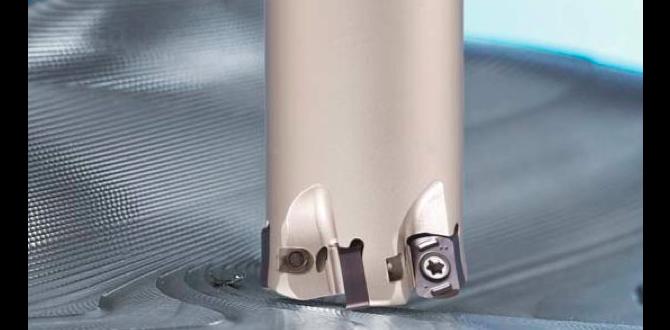
When we refer to a “stub length” carbide end mill, it means the flute length is shorter than the overall length of the tool. This is often beneficial for rigidity, meaning the bit is less likely to flex or chatter, leading to cleaner cuts and a longer tool life, especially when you’re not using a coolant to support it. For FR4 dry cutting, a stubby, sharp carbide end mill is your best friend.
Why Dry Cutting FR4?
You might wonder why we’d specifically talk about “dry cutting.” In metalworking, coolants are often essential to keep tools from overheating and to flush away chips. However, with FR4 and small carbide bits on a CNC router or mill, dry cutting can be perfectly effective and has several advantages, particularly for hobbyists and those working in a home workshop:
Cleanliness: No coolant mess means no cleanup of oily or milky fluid. Your workshop stays cleaner.
Simplicity: You don’t need to set up a coolant system or worry about filtering or disposing of used coolant.
Material Integrity: For certain PCB designs, especially those sensitive to moisture or contamination, dry cutting can be beneficial.
Cost-Effectiveness: Eliminates the cost of coolant.
The key to successful dry cutting FR4 with a 1/8 inch carbide end mill is using plenty of air for cooling and chip evacuation, combined with appropriate feed rates and spindle speeds.
Tools and Materials You’ll Need
Before you start, gather everything you need. This makes the process much smoother and safer.
CNC Machine: A desktop CNC router or a milling machine capable of precise movements.
1/8 Inch Carbide End Mill: Specifically designed for plastics or composites, with a 3.175mm shank. A 2-flute end mill is often recommended for its chip-clearing capabilities in dry cutting. Look for bits with a bright, sharp edge.
FR4 PCB Material: The material you want to cut. Ensure it’s clean and flat.
Workholding: Clamps, double-sided tape, or a vacuum table to securely hold the FR4 material to your CNC bed. A rigid hold is essential to prevent movement during cutting.
Dust Collection (Highly Recommended): FR4 dust can be an irritant. A shop vacuum with a dust shoe attached to your CNC spindle is ideal for collecting the dust at the source.
Safety Glasses: Always wear safety glasses to protect your eyes from flying debris and dust.
Hearing Protection: CNC machines can be loud.
Respirator/Dust Mask: Recommended for FR4 dust.
Calipers: To measure and verify dimensions.
Cutting Fluid (Optional, for specific cases): While we focus on dry cutting, in some extreme cases or with less-than-ideal airflow, a mist coolant can be used sparingly, but it’s generally avoided for pure dry cutting setups. For this guide, we’re assuming dry cutting.
Choosing the Right End Mill
For FR4 dry cutting with a 1/8 inch shank, consider these end mill features:
Material: Solid Carbide is a must.
Flute Count: 1 or 2 flutes are generally preferred for plastics and composites like FR4. More flutes (like 4) can lead to better surface finish but produce smaller chips and can overload the flutes with debris in dry cutting if not managed carefully with feed rates. So, for beginner dry cutting of FR4, a 2-flute end mill is a solid choice.
Coating: Uncoated carbide bits work well, but some specialized coatings can improve performance and tool life. For plain FR4 dry cutting, uncoated is usually sufficient and cost-effective.
Helix Angle: A standard helix angle (often around 30 degrees) works well. Very high helix angles can sometimes be beneficial for plastics but aren’t essential for basic FR4 work.
“Stub” or “Short” Length: As mentioned, these are generally more rigid. For a 1/8 inch shank, you’ll often find flute lengths from 1/8″ to 1/2″ which are considered stubby.
Here’s a quick comparison of flute counts for FR4 dry cutting:
| Flute Count | Pros for FR4 Dry Cutting | Cons for FR4 Dry Cutting |
|---|---|---|
| 1 or 2 Flutes | Excellent chip evacuation, less prone to clogging, good for faster feed rates, generally ideal for dry cutting. | Can sometimes result in a slightly rougher surface finish compared to higher flute counts, but this is often negligible on PCB material. |
| 3 or 4 Flutes | Can provide a smoother surface finish, better for plunge cuts in some materials. | Chips are smaller and can pack more easily in the flutes, increasing the risk of clogging and overheating in dry cutting. Requires slower feed rates to manage chip load. |
For beginners focusing on dry cutting FR4 with a 1/8 inch carbide end mill, the 2-flute stub length carbide end mill is usually the recommended choice.
Step-by-Step Guide to Dry Cutting FR4
Cutting FR4 with a 1/8 inch carbide end mill on your CNC machine is a straightforward process once you understand the key settings. Here’s how to do it safely and effectively.
Step 1: Secure Your FR4 Material
This is critical. Any movement of the material during cutting will ruin your cut and potentially damage your end mill or machine.
Clean the Surface: Make sure the underside of your FR4 and the surface of your CNC bed are clean. Dust and debris can prevent a good seal if using tape or a vacuum table.
Methods of Workholding:
Double-Sided Tape: For thin FR4 sheets, strong double-sided PCB tape or carving tape can work well. Apply it evenly to the back of the FR4.
Clamps: If your FR4 is thick enough to not be damaged by clamp tips, use edge clamps to hold it firmly against the machine bed.
Vacuum Table: The most professional and effective method, if your CNC has one.
Ensure the material is perfectly flat and immoveable.
Step 2: Set Up Your CNC and End Mill
Install the End Mill: Insert the 1/8 inch carbide end mill into your CNC spinde’s collet. Make sure it’s seated properly and tightened securely.
Connect Dust Collection: If you have a dust shoe, attach your vacuum hose to it. Ensure it’s positioned so it effectively captures dust during cutting.
Zero the Z-Axis: This is crucial for accurate depth control.
Place a known flat surface (like a piece of scrap FR4 or a small metal block) on your CNC bed where you intend to zero.
Manually lower the spindle until the tip of the end mill just touches the surface.
Use your CNC controller’s interface to “Set Z Zero.”
Step 3: Configure Your CAM Software (for Toolpath Generation)
This is where you tell your CNC what to cut. You’ll need software that can generate G-code from your design (CAD/CAM software).
Import Your Design: Load your PCB design (often as an SVG, DXF, or Gerber file).
Define Stock Thickness: Enter the thickness of your FR4 material.
Choose Cutting Strategy:
For cutting out the perimeter of a PCB, you’ll typically use a “Pocket” or “Contour” operation. If you’re milling traces, you’ll use a “Pocket” for isolation.
Set Tool Parameters:
Tool Diameter: 1/8 inch (3.175mm)
Number of Flutes: 2
Spindle Speed (RPM): For FR4 and a 1/8″ carbide bit, a good starting point is between 18,000 to 24,000 RPM. Higher speeds can help with surface finish but generate more heat. If you’re experiencing melting, you might need to consider slightly slower speeds or better air cooling.
Feed Rate (IPM or mm/min): This is how fast the tool moves through the material. For FR4 dry cutting with a 1/8″ 2-flute carbide bit, a common starting point is 20-40 inches per minute (IPM) or 500-1000 mm/min. This is a critical setting to get right to avoid melting. If the bit loads up with material or melts, slow down the feed rate.
Plunge Rate: This is how fast the tool moves downwards into the material. It should generally be slower than the feed rate to prevent jamming. A good starting point is 10-20 IPM or 250-500 mm/min.
Depth per Pass (Stepdown): For FR4, you don’t want to cut the full depth in one go. Take shallower passes to reduce stress on the bit and improve chip evacuation. For a 1/8″ bit, a stepdown of 0.06 to 0.12 inches (1.5mm to 3mm) per pass is often recommended, depending on your machine’s rigidity.
Stepover: This is how much the tool overlaps on adjacent passes when milling an area (like a pocket). For contour cutting, it’s usually set to 100% (the diameter of the tool). For pocketing traces, it might be set to 20-50% of the tool diameter.
Generate G-code: Once all parameters are set, generate your G-code.
Step 4: Perform a Dry Run (Air Cut)
Before you cut into your actual FR4, it’s highly recommended to run your G-code with the spindle off (or raised significantly) to simulate the cutting path.
Observe Movement: Watch the machine to ensure the toolpaths are as expected and don’t crash into any clamps or hold-downs.
Check for Collisions: Confirm that your dust shoe or any other part of the machine won’t interfere with the cutting operations.
Step 5: The First Cut
Turn on Spindle and Dust Collection: Start your spindle to the programmed speed and ensure your dust collection system is running at full power.
Initiate Z-Axis Movement: Start the Z-axis plunge at a safe height and at your set plunge rate to begin cutting.
Monitor the Process: Keep a close eye on the cutting.
Sound: Listen for any unusual noises. A smooth, consistent sound is good. A grinding or chattering sound might indicate an issue.
Chips: Observe the chips being produced. They should be relatively small, dry particles. If they are large, stringy, or melting, your feed rate might be too slow, or your spindle speed too high.
Melting: Look for signs of melting on the edges. If you see melting, stop the machine immediately. You may need to adjust your feed rate (increase it slightly) or spindle speed (decrease it slightly). Sometimes, a slight increase in air blast can also help.
Dust: Ensure your dust collection is working effectively.
Step 6: Finishing the Cut
Your CNC will continue to follow the G-code path. If cutting a full perimeter, it will make one or more passes until the desired depth is reached.
Depth Control: Ensure your “Depth per Pass” settings are appropriate. For a typical 1.6mm (0.063 inch) PCB, one or two passes might be sufficient for the entire cut-out. For thicker material, you’ll need more passes.
Final Pass: The last pass is often set to the exact material thickness to ensure a clean separation.
Step 7: Clean Up
Once the cutting is complete and the spindle has stopped:
Wait for Spindle to Stop: Do not try to remove the part while the spindle is still spinning.
Remove Part: Carefully lift your newly cut FR4 piece from the machine bed. You may need to gently cut through any small tabs (if your CAM software generated them for holding the part) with a craft knife or break it off by hand if it’s small enough.
Inspect the Cut: Examine the edges. They should be clean and smooth, with no signs of melting or chipping.
Clean Your Machine: Vacuum up any remaining dust. Clean your end mill if necessary.
Important Considerations for FR4 Dry Cutting
Airflow is Key: For dry cutting FR4, a strong blast of air directed at the cutting point is your primary cooling and chip-clearing mechanism. Many CNC machines have an air blast nozzle that can be positioned to blow air directly into the cut.
Chip Load: This is the amount of material removed by each cutting edge on one rotation. It’s determined by your feed rate, spindle speed, and number of flutes. Maintaining an appropriate chip load prevents the bit from overheating and melting the material. For FR4, a relatively light chip load is usually best.
Tool Wear: Even carbide wears down. If you notice your cuts becoming rougher or melting starts to occur more frequently, it might be time to replace your end mill. A 1/8 inch carbide end mill is relatively inexpensive, so don’t hesitate to swap it out when it’s no longer performing well.
Optimizing Your Settings for FR4
Finding the perfect settings for your specific CNC machine, end mill, and FR4 material can involve a bit of trial and error. However, here’s a more detailed breakdown to help you dial in your parameters. Remember, these are starting points.
Spindle Speed (RPM)
General Range: 18,000 – 24,000 RPM
Why this range? Carbide needs high speeds to cut effectively. Lower speeds with carbide often lead to rubbing rather than cutting, generating excess heat and causing melting.
Adjustments:
If melting occurs: Try slightly increasing RPM.
If surface finish is poor (fibrous): Try slightly decreasing RPM or increasing feed rate.
Most hobby CNCs are limited in their highest RPM if using a DC spindle without a VFD. Ensure your spindle can reach these speeds reliably.
Feed Rate (IPM / mm/min)
General Range: 20 – 40 IPM (500 – 1000 mm/min) for a 1/8″ 2-flute end mill.
Why this range? This directly affects the chip load. A balanced feed rate ensures that enough material is being removed by each flute to create a proper chip, which then gets cleared away. Too slow, and the bit rubs and melts; too fast, and you risk breaking the bit or overloading the motor.
Adjustments:
If melting or chip welding occurs: Increase feed rate. This is often the most effective solution.
If the bit is chattering or producing a rough finish: Try decreasing feed rate slightly, or check your workholding and machine rigidity.
*