Quick Summary
Successfully using a 1/8-inch carbide end mill with a 3/8-inch shank, specifically a reduced neck design for heat resistance, to machine 7075 aluminum requires understanding tool geometry, proper speeds and feeds, secure workholding, and essential safety measures. This guide provides a clear, step-by-step approach for beginners.
Mastering the 1/8-Inch Carbide End Mill for 7075 Aluminum: A Beginner’s Guide
Working with aluminum, especially a tough alloy like 7075, might seem daunting at first, but with the right tools and knowledge, it becomes an achievable and rewarding part of your machining journey. Today, we’re focusing on a specific, yet incredibly versatile tool: the 1/8-inch carbide end mill with a 3/8-inch shank, and importantly, one with a reduced neck designed for heat resistance. This combination is perfect for intricate work on aluminum, and this guide will walk you through everything you need to know, from selecting the right bit to making those perfect cuts safely and effectively. Get ready to take your projects to the next level!
Understanding Your Tool: The 1/8-Inch Carbide End Mill
Let’s break down what makes this particular end mill so useful, especially for beginners tackling challenging materials like 7075 aluminum.
Anatomy of the End Mill
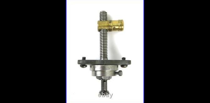
A carbide end mill is a cutting tool with a shank (the part that goes into the spindle) and cutting flutes (the spiral grooves that do the actual cutting). For our discussion, the key features are:
Carbide Material: This powerhouse material is extremely hard and wears down much slower than high-speed steel (HSS). This means it can cut harder materials, run at higher speeds, and maintain its sharp edge for longer, which is crucial for consistent results.
1/8-Inch Cutting Diameter: This small diameter is ideal for detailed work, creating small pockets, slots, or intricate features. It offers precision but also means it’s more susceptible to breakage if not used correctly.
3/8-Inch Shank: This is the diameter of the toolholder shank. A 3/8-inch shank is common and provides good rigidity.
Reduced Neck: This is a critical feature for our application. The neck is the part of the tool just above the cutting flutes. When it’s “reduced,” it means this section is made to be smaller in diameter than the cutting diameter. This is vital for heat dissipation and preventing the tool from rubbing within deep cuts, which can lead to overheating and premature wear, a common issue when machining aluminum.
Heat Resistance: Often indicated by coatings or specific carbide grades, heat resistance is paramount when machining aluminum. Aluminum tends to be “gummy” and can generate significant heat, leading to chip welding and tool failure.
Why Carbide for 7075 Aluminum?
7075 aluminum is a high-strength alloy, often compared to steel in its hardness. Machining it effectively requires a tool that can withstand higher cutting forces and temperatures without deforming or softening. Carbide is the clear winner here due to its superior hardness and high-temperature strength.
Choosing the Right End Mill: Key Considerations
Not all 1/8-inch carbide end mills are created equal, especially when dealing with specific materials and desired outcomes.
Flute Count
2-Flute: Generally preferred for softer materials like aluminum. The increased chip clearance helps prevent chip welding and allows for higher feed rates. This is often the go-to for aluminum.
3-Flute or 4-Flute: While better for steel and other harder metals due to increased rigidity and better surface finish, they can clog up more easily with aluminum, leading to overheating.
For machining 7075 aluminum with a 1/8-inch end mill, a 2-flute design with excellent chip evacuation capabilities is usually best.
Coatings
While not always necessary for aluminum, certain coatings can further enhance performance and tool life.
ZrN (Zirconium Nitride): Can offer good lubricity, reducing friction and heat.
AlTiN (Aluminum Titanium Nitride) or TiAlN (Titanium Aluminum Nitride): Primarily for high-temperature applications in steels, less common for aluminum but can sometimes be used.
For 7075 aluminum, an uncoated or ZrN-coated end mill is typically a good starting point.
End Type
Square End: The most common type, used for creating flat-bottomed slots and pockets.
Ball Nose: Used for creating curved surfaces or rounding corners.
Corner Radius: A square end with a small radius on the corners, adding some strength to the tool while still allowing for sharp internal corners.
For general-purpose machining of 7075 aluminum, a square end or a corner radius end mill will cover most needs.
Reduced Neck Design
As mentioned, this is crucial for 7075 aluminum. The reduced neck allows the body of the end mill to pass through a slot or hole without rubbing against the material, significantly reducing friction and heat buildup. This prevents chip welding and extends tool life. Always look for this feature for gummy materials or deeper cuts.
Setting Up for Success: Workholding and Machine Preparation
Before you even think about cutting, securing your workpiece and preparing your machine are paramount for safety and precision.
Workholding: The Foundation of Machining
Your 7075 aluminum workpiece needs to be held as rigidly as possible. Any movement during cutting will lead to poor surface finish, inaccurate dimensions, and potentially tool breakage.
Vise: A good quality machine vise is the most common and effective method. Ensure the vise jaws are clean and parallel. Use soft jaws if you are concerned about marring the surface of your aluminum.
Clamps: For larger or irregularly shaped parts, T-slot clamps can be used directly on the machine table. Ensure they are placed strategically to provide maximum support and prevent lifting.
Fixturing: For production runs or very precise operations, custom fixtures are often made. This might be too advanced for a beginner’s first cut, but it’s good to be aware of.
Key Workholding Tips:
Always clamp on the solid mass of the workpiece, not on thin sections that could deflect.
Ensure the workpiece is indicated perfectly square or parallel to the machine axes, as needed.
Use parallels or riser blocks in a vise for better jaw contact and to allow cutting below the top jaw surface.
Machine Preparation
Cleanliness: Ensure your machine’s table, spindle, and tool holder are clean. Dust, chips, or coolant residue can cause issues.
Spindle Taper: Make sure the spindle taper and the tool holder taper are clean and free of debris for a secure fit.
Tool Holder: Use a high-quality collet chuck or a shrink-fit holder for best concentricity and rigidity when holding your end mill. A standard R8 collet can also work but might offer less rigidity than a specialized tool holder.
Speeds and Feeds: The Heart of Machining Aluminum
This is often the most intimidating part for beginners, but it’s essential for successful machining, especially with 7075 aluminum and a small carbide end mill.
Understanding the Concepts
Spindle Speed (RPM): How fast the cutting tool rotates. Measured in revolutions per minute.
Feed Rate (IPM/mm/min): How fast the tool moves through the material. Measured in inches per minute (IPM) or millimeters per minute.
Chip Load: The thickness of the chip that each cutting edge of the end mill removes. This is a critical factor for tool life and surface finish. Too thin a chip can cause rubbing and overheating; too thick a chip can overload the tool.
Calculating Speeds and Feeds for 7075 Aluminum
There are formulas and charts, but for a beginner, it’s often easier to start with recommended values and adjust.
General Guidelines for Carbide End Mills in Aluminum:
Surface Speed (SFM – Surface Feet per Minute): For carbide in aluminum, this can range from 300 to 800 SFM, depending on the specific alloy, tool coating, and lubrication. For 7075 with a standard carbide end mill, aiming for the lower to middle end of this range is safer.
Chip Load per Flute: For a 1/8-inch end mill, a chip load of 0.001″ to 0.002″ per flute is a good starting point for softer aluminum. For 7075, you might need to be at the lower end or slightly above, depending on rigidity and coolant.
Let’s calculate for a 1/8″ (0.125″) Carbide End Mill:
1. Choose a Surface Speed (SFM): Let’s start with 400 SFM for 7075 aluminum.
2. Calculate Spindle Speed (RPM):
Formula: RPM = (SFM 12) / (Tool Diameter π)
RPM = (400 12) / (0.125 3.14159)
RPM = 4800 / 0.3927
RPM ≈ 12,223 RPM (This is very high for many home hobbyist machines. We’ll adjust this.)
This calculation highlights why machine capability is important! Most small hobby machines can’t reach such speeds. For practical purposes on typical benchtop CNCs or manual mills, you’ll often use much lower speeds with carbide in aluminum, relying more on feed rate and lubrication to manage heat.
Practical Approach for Lower RPM Machines:
Let’s assume your machine can only do 5,000 RPM.
Spindle Speed: Let’s set it to a middle-ground for hobby machines: 3,000 – 5,000 RPM.
Chip Load per Flute: Let’s aim for 0.0015″ per flute.
Feed Rate (IPM):
Formula: Feed Rate = RPM Number of Flutes Chip Load per Flute
Feed Rate = 3,000 RPM 2 Flutes 0.0015″
Feed Rate = 9 IPM
Table: Starting Speeds and Feeds for 1/8″ Carbide End Mill in 7075 Aluminum
| Parameter | Value | Notes |
| :—————– | :——————- | :—————————————————————— |
| Spindle Speed | 3,000 – 5,000 RPM | Adjust based on your machine’s capability and rigidity. |
| Feed Rate | 6 – 12 IPM | Start at the lower end and increase if the cut is smooth. |
| Chip Load/Flute| 0.001″ – 0.002″ | Crucial for preventing chip welding. |
| Depth of Cut | 0.050″ – 0.100″ (Radial) | For full slotting, reduce radial depth. |
| Depth of Cut | 0.125″ – 0.250″ (Axial) | Consider stepping down for deeper cuts. |
| Lubrication | Flood, Mist, or Air | Essential for chip evacuation and cooling. |
Important Considerations:
Rigidity: If your setup “chatters” or vibrates, reduce feed rate or depth of cut.
Chip Load is King: Focus on maintaining a good chip load.
Listen to Your Machine: A smooth humming sound is good. A screeching or grinding sound is bad.
Step Down: For complex pockets, don’t try to remove all the material in one pass. Use multiple shallow passes.
Machining Techniques for 7075 Aluminum
How you remove material matters. Here are effective techniques for using your end mill.
Slotting vs. Pocketing
Slotting: Cutting a channel or slot that goes all the way through your part or to a specific depth. With a 1/8” end mill, this means the cutting diameter is the width of your slot.
Pocketing: Machining out a larger area to a certain depth. This typically involves a series of passes, often using a roughing strategy to remove bulk material efficiently, followed by a finishing pass.
Milling Strategies
Conventional Milling: The cutter rotates against the direction of feed. This is generally better for harder materials or less rigid setups as it lifts the chip.
Climb Milling (Helical Milling): The cutter rotates in the same direction as the feed. This produces a better surface finish and reduces cutting forces, making it ideal for aluminum. However, it requires a machine with no backlash in the feed system (like most modern CNCs) or very careful technique on manual machines.
For 7075 Aluminum with a weak setup, start with conventional milling to avoid forcing the tool. For CNC users with rigid machines, climb milling will yield superior results.
Using the Reduced Neck Advantage
The reduced neck is designed to prevent rubbing. This means you can often achieve better results in deeper pockets or narrower slots where tool clearance is tight. Always ensure that the reduced neck is actually below the surface of your cut to gain the full benefit.
Coolant and Lubrication
Aluminum is notorious for its tendency to “gum up” cutting tools. Proper lubrication is essential.
Flood Coolant: The most effective but requires a system.
Mist Coolant: A fine spray of coolant and air, very effective for aluminum and suitable for most machines.
Air Blast: A strong blast of compressed air can help clear chips and provide some cooling.
Cutting Fluid/Lube Sticks: Apply directly to the cutting area periodically. Specialized aluminum cutting fluids are available.
For 7075 aluminum, I highly recommend using a mist coolant system or a specific aluminum cutting fluid.
Safety First: Always Prioritize Protection
Machining, even on a small scale, involves inherent dangers. Always follow these safety precautions.
Personal Protective Equipment (PPE)
Safety Glasses: Absolutely non-negotiable. Always wear ANSI-approved safety glasses or a full face shield, especially when the machine is running. Chips can fly unpredictably.
No Loose Clothing or Jewelry: Long sleeves, ties, necklaces, or rings can get caught in rotating machinery.
Gloves: Wear cut-resistant gloves when handling sharp tools or parts, but never when the machine is operating.
Hearing Protection: While often overlooked for smaller machines, prolonged exposure to machine noise can damage hearing.
Machine Safety
Secure Workpiece: Double-check that your workpiece is firmly clamped. A tool hitting loose material can cause serious damage or injury.
Secure Tooling: Ensure the end mill is properly tightened in its holder and the holder is securely in the spindle.
Use Correct Speeds and Feeds: Never force a tool or run it too fast.
Clear Chips Safely: Never use your hands to clear chips from a machine while it’s running or still spinning down. Use a brush, shop vacuum, or compressed air after the spindle has stopped.
Keep Area Clean: A tidy workspace reduces the chance of tripping or knocking things over.
Know Your Emergency Stop: Be familiar with the location and operation of your machine’s emergency stop button.
Step-by-Step Guide: Machining a Simple Slot in 7075 Aluminum
Let’s put theory into practice with a basic example. We’ll machine a 1/4-inch wide slot. Since our end mill is 1/8-inch (0.125″), we’ll need to make multiple passes across the width.
Step 1: Prepare Your Workpiece and Machine
1. Clean your 7075 aluminum block and your vise.
2. Place the aluminum block in the vise, ensuring it’s securely held and square. Use parallels if needed for better clamping.
3. Clean the machine spindle and your collet chuck.
4. Insert the 1/8-inch carbide end mill into the collet, ensuring it’s seated correctly and tightened securely. Make sure the entire length of the shank is supported if possible.
5. Mount the tool holder into the machine spindle.
Step 2: Set Up Speeds, Feeds, and Depth
1. Based on our earlier calculations for a 3,000 RPM spindle motor:
Feed Rate: 9 IPM (for 2-flute, 0.0015″ chip load)
2. Determine your depth of cut. For a slot, assume you want to go down 0.100 inches in total.
Pass Depth: Let’s take 0.050″ per pass. So, two passes will reach 0.100″.
Step 3: Zero Axes and Initial Plunge
1. Carefully bring the end mill down to the surface of your aluminum block. Use an edge finder or a piece of paper rolled up for a rough Z-zero.
2. Set your X and Y zeros where you want the slot to start.
3. Engage your mist coolant or cutting fluid.
4. Plunge: Slowly feed the end mill vertically into the material to the depth of your first pass (0.050″). Use a controlled plunge rate