
Carbide end mills with optimized flute geometry are key to effective cast iron chip evacuation, preventing tool wear and improving surface finish. Choosing the right end mill and machining strategy ensures clean cuts and prolonged tool life.
Working with cast iron on the mill can be a bit tricky. One of the biggest headaches for beginners is dealing with chips. They can build up, clog flutes, and cause all sorts of problems. This is especially true when you’re looking for that perfect surface finish. But don’t worry! With the right carbide end mill and a few smart techniques, you can master cast iron chip evacuation. Let’s dive in and get those chips flying out cleanly.
Understanding Cast Iron Chip Evacuation Challenges
Cast iron is a fantastic material for many projects, but cutting it can present unique challenges, especially when it comes to chip evacuation. Unlike softer metals, cast iron tends to produce small, abrasive chips. These chips are like tiny bits of sandpaper in your cutting zone.
If these chips don’t escape properly, they can:
- Weld to the tool: Stuck chips can cause the end mill to overheat and dull faster, leading to poor cut quality.
- Recutting: The chips get pushed back into the fresh cut, creating a rough surface finish and increasing cutting forces.
- Tool breakage: Excessive heat and chipping can weaken the end mill, making it prone to snapping.
- Overheating the workpiece: Poor evacuation means heat is concentrated in one spot, which isn’t good for your part or your machine.
The goal is to get these stubborn cast iron chips out of the flutes and away from the cutting area as quickly and efficiently as possible. This is where the right carbide end mill design comes into play.
The Role of Carbide End Mills in Chip Evacuation
Carbide end mills are the go-to choice for machining tougher materials like cast iron. Their hardness and heat resistance make them ideal. But not all carbide end mills are created equal when it comes to chip evacuation. The secret lies in their flute design and geometry.
Here’s what makes a carbide end mill excel at clearing cast iron chips:
- Helix Angle: A steeper helix angle (often 45 degrees or more) helps to lift and eject chips more effectively from the fluted area. Think of it like a conveyor belt for chips.
- Number of Flutes: For materials like cast iron, fewer flutes (2 or 3) are generally better for chip evacuation. More flutes mean less space for chips to escape. We’ll discuss this more later.
- Core Thickness: A robust core (the solid part in the center of the end mill) provides strength, which is important for resisting the forces involved in cutting cast iron. It shouldn’t be so thick, however, that it impedes chip flow.
- Rake Angle: The angle on the cutting edge influences how the chip is formed and flows away from the tool. Optimized rake angles help manage chip formation.
- Coatings: Special coatings, like TiAlN (Titanium Aluminum Nitride), can improve lubricity and heat resistance, further aiding in chip control and preventing buildup.
Choosing the Right Carbide End Mill for Cast Iron
When you’re starting out, selecting the correct end mill can feel overwhelming. For cast iron chip evacuation, you want an end mill specifically designed for this purpose. Let’s break down the key factors to consider.
Key End Mill Features for Cast Iron
- Material: Solid carbide is a must for cast iron due to its hardness and wear resistance.
- Flute Count:
- 2-Flute: Often the best choice for cast iron. The larger flute opening provides excellent chip clearance, crucial for preventing chip packing.
- 3-Flute: A good compromise if you need a bit more rigidity than a 2-flute but still want decent chip evacuation. More flutes mean less clearance.
- 4-Flute: Generally less ideal for cast iron chip evacuation because the smaller flute openings can easily become clogged. Better for finishing or aluminum.
- Helix Angle: Look for end mills with higher helix angles, typically 30 degrees up to 45 degrees or even 60 degrees. These steeper angles help “screw” the chips up and out of the hole.
- Corner Radius: A small corner radius can add strength to the cutting edge and help with finish. However, for aggressive roughing where chip evacuation is paramount, a square end might be preferred, though it can be more prone to chipping on the corners.
- Shank: A plain shank is standard. If you need extra holding force in a collet chuck or hydro-tool holder, a Weldon shank with a flat is beneficial.
- Length of Cut (LOC) and Overall Length (OAL): Ensure the end mill is long enough to reach your desired cutting depth. For cast iron, sometimes shorter, more rigid end mills can perform better by minimizing deflection.
- Coatings: For cast iron, AlTiN (Aluminum Titanium Nitride) or TiAlN are excellent choices. They provide a hard, heat-resistant layer that reduces friction and prevents chip welding.
Example: The “Carbide End Mill 1/8 Inch 3/8 Shank Long Reach for Cast Iron Chip Evacuation”
Let’s consider a specific example like the keyword suggests: “carbide end mill 1/8 inch 3/8 shank long reach for cast iron chip evacuation.”
- 1/8 inch diameter: This can be useful for detailed work or smaller parts. For this size, chip evacuation can be more challenging due to the small flute volumes.
- 3/8 inch shank: Provides good rigidity and compatibility with common milling machine collets.
- Long Reach: This implies a longer overall length. While useful for reaching into deep pockets, longer tools can be more prone to vibration and deflection, which can negatively impact chip evacuation. For cast iron, a balance between reach and rigidity is often best. A “medium” reach might be more beneficial than an extremely long one for optimal chip evacuation.
- For Cast Iron Chip Evacuation: This highlights the critical features we’ve discussed – likely a 2-flute design with a good helix angle and a suitable coating.
When looking for such an end mill, you’d want to confirm its specifications: 2-flute, high helix (e.g., 30-45 degrees), AlTiN or TiAlN coating. The “long reach” aspect needs careful consideration; if reach compromises rigidity significantly, it might hinder evacuation.
Essential Machining Strategies for Cast Iron Chip Evacuation
Even with the perfect end mill, your machining strategy plays a huge part in how well chips are evacuated. It’s not just about the tool; it’s about how you use it.
1. Depth of Cut (ADOC) and Width of Cut (AOC)
This is crucial. You want to use a shallow depth of cut and a relatively narrow width of cut. This allows the flutes to do their job of clearing chips without becoming overloaded.
- Shallow Depth of Cut: Taking smaller bites means less material is being removed at once, and the chips are smaller and easier to eject.
- Moderate Width of Cut: Avoid “full width” slotting where possible, as this restricts chip flow significantly. Aim for a width of cut that’s typically 25-50% of the end mill’s diameter.
2. Slotting Strategies
When you need to make a slot, the standard “plunge and walk” method is terrible for chip evacuation on cast iron. Instead, consider these:
- Helical Interpolation (Ramping): This is the most effective method. The end mill moves in a helix (like a spring) as it plunges and moves sideways, creating a circular interpolation. This path constantly clears chips and reduces cutting forces. You can find calculators online to help determine the G-code for helical boring.
- Pencil Milling (Engraving): For very narrow features or tight clearances, taking short, sweeping cuts along the edge of your desired slot. This is slow but can work well if helical interpolation isn’t feasible.
- Conical Milling: Similar to helical interpolation, but the path is more conical, helping to break up chips.
For a beginner, practicing ramping is highly recommended. Many CNC machines have built-in cycles for this, or you can program it manually. For manual milling, using a rotary table can facilitate similar motion.
3. Feed Rate (IPM/mm/min)
Don’t confuse feed rate with cutting speed. The feed rate dictates how fast the tool moves through the material. For cast iron, you generally want a moderate to high feed rate. A faster feed rate helps push chips out of the flutes more forcefully. However, the feed rate must be balanced with the spindle speed to maintain the correct chip load (the amount of material each cutting edge removes per revolution).
Chip Load is Key: Manufacturers provide recommended chip loads for their end mills. Calculate your desired feed rate using the formula: Feed Rate = Chip Load × Number of Flutes × Spindle Speed.
4. Spindle Speed (RPM)
Spindle speed determines the Surface Feet Per Minute (SFM) or Surface Meters Per Minute (SMM). For cast iron, typical cutting speeds for solid carbide range from 200-400 SFM (or around 60-120 SMM). You need to calculate the appropriate RPM based on your end mill diameter and the recommended SFM:
RPM = (SFM × 12) / (π × Diameter)
Always start conservatively and listen to the cut. If chips aren’t clearing, a slight adjustment might be needed.
5. Coolant and Lubrication
While often machined dry, a small amount of coolant or a good quality mist system can significantly help with chip evacuation and tool life in cast iron.
- Lubrication: A light mist of cutting fluid can help the chips flow more easily and reduce friction. Many machinists prefer a dry-cut strategy for cast iron to avoid making a mess and to keep heat in the chip rather than the tool, but a little bit of lubricity can be beneficial.
- Air Blast: A powerful air blast directed at the cutting zone is extremely effective at blowing chips clear of the flutes and off the workpiece. This is often the preferred method for dry machining cast iron.
- Through-Spindle Coolant (TSC): If your machine has TSC, it’s excellent, but ensure it’s an oil-based lubricant suitable for cast iron, as water-based coolants can sometimes cause rust.
6. Climb Milling vs. Conventional Milling
For chip evacuation, climb milling often has an advantage. In climb milling, the cutter rotates in the same direction as the feed. This pulls the chip away from the cutting edge more cleanly.
- Climb Milling: Tool rotation and feed motion are in the same direction. Chips are cleared away.
- Conventional Milling: Tool rotation and feed motion are in opposite directions. This tends to push chips into the flute and can create more heat.
Unfortunately, many manual milling operations default to conventional milling due to machine backlash. If you have a CNC mill with minimal backlash, climb milling is generally superior for chip evacuation and finish.
Step-by-Step: Roughing Cast Iron for Optimal Chip Evacuation
Let’s walk through a common scenario: roughing out a pocket in a cast iron block.
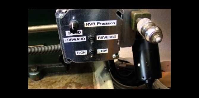
Tools and Setup You’ll Need:
- Milling Machine: CNC or capable manual mill.
- Solid Carbide End Mill: 2-flute, AlTiN or TiAlN coated, with a ~30-45 degree helix angle. Diameter appropriate for your pocket size (e.g., 1/4″ or 3/8″).
- Collet Chuck or Tool Holder: For secure tool holding.
- Workholding: Vise or clamps securely holding the cast iron block.
- Measuring Tools: Calipers, dial indicator for setup.
- Safety Gear: Safety glasses, hearing protection, gloves (when handling stock, not during operation).
- Lubrication/Coolant (Optional but recommended): Mist system, air blast, or cutting fluid.
Procedure:
- Secure the Workpiece: Mount your cast iron block firmly in the milling vise. Ensure it’s as rigid as possible.
- Install the End Mill: Place your selected 2-flute carbide end mill into the collet chuck and tighten it securely. Ensure the shank is well-supported.
- Set Up Z-Zero: Carefully set your Z-axis zero point. For pockets, this is typically the top surface of the workpiece.
- Determine Cutting Parameters:
- Spindle Speed (RPM): Calculate based on your end mill diameter and recommended SFM (e.g., 300 SFM for a 1/4″ end mill: RPM = (300 12) / (3.14159 0.25) ≈ 4584 RPM).
- Chip Load: Consult the end mill manufacturer’s data. A common starting point for a 1/4″ end mill might be 0.002″ – 0.004″ per tooth.
- Feed Rate: Calculate: Feed Rate = Chip Load × Number of Flutes × Spindle Speed. For 0.003″ chip load, 2 flutes, at 4584 RPM: Feed Rate = 0.003 2 4584 ≈ 27.5 IPM. Adjust based on machine capability.
- Depth of Cut (ADOC): Start conservative for cast iron, especially roughing. For a 1/4″ end mill, 0.050″ to 0.100″ is a good starting point.
- Width of Cut (AOC): For pocketing, use a stepover (width of cut) of about 30-40% of the end mill diameter (e.g., 0.075″ – 0.100″ for a 1/4″ end mill). For slotting, use a narrower stepover if not using helical interpolation.
- Initiate Tool Path:
- For Pockets: Use an appropriate entry method. A helical ramping motion, even if it doesn’t complete a full circle, is ideal for entering the material. If your CAM software doesn’t support it or for manual milling, use a plunge move with a feed rate that is significantly slower than your cutting feed rate (e.g., 1/3 to 1/2). For aggressive plunging, consider a specialized plunge end mill if available, but a standard 2-flute end mill can plunge carefully.
- For Slotting: Always use helical interpolation if possible. If not, plunge carefully and remove material in multiple passes, ideally with a narrower-than-preferred width of cut, allowing for axial chip removal.
- Engage Spindle and Feed: Start the spindle at the calculated RPM. Once at speed, engage the feed rate. Activate your air blast or mist system.
- Monitor the Cut: Listen to the sound of the machine. A smooth hum is good. Chattering or squealing indicates an issue. Observe the chips – they should be relatively small and ejected cleanly from the flutes. If you see chip buildup, reduce the depth of cut or feed rate slightly.
- Complete the Pocket: Let the end mill perform its programmed path. Observe for any signs of trouble.
- Retract and Inspect: Once the pass is complete, retract the end mill clear of the workpiece. Turn off the spindle and inspect the chips and the machined surface. The surface should be relatively smooth, and the chips should have been cleared effectively.
- Adjust and Repeat (if necessary): Based on your observation, fine-tune your parameters. For deeper pockets, you’ll likely need multiple passes, increasing the depth of cut incrementally or incrementally adding to the Z depth. Ensure each subsequent pass continues to clear chips effectively.
Comparing Chip Evacuation Performance
To illustrate the differences, let’s compare common end mill types for cast iron chip evacuation.
Related Posts

| End Mill Type | Flute Count | Helix Angle | Chip Evacuation | Best For | Considerations |
|---|---|---|---|---|---|
| Standard 4-Flute (General Purpose) | 4 | 30 degrees | Poor to Fair | Finishing, Aluminum | Flutes clog easily in cast iron; risk of chip recutting and tool breakage. |
| High-Performance 2-Flute (for Aluminum) | 2 |