Can a 1/8-inch carbide end mill cut cast iron reliably? Yes, a 1/8-inch carbide end mill is proven effective for machining cast iron, especially when it’s designed for ferrous materials and used with appropriate speeds and feeds. Choosing the right geometry and coolant is key for achieving tight tolerances and a smooth finish on this tough material.
Hey there, machining enthusiasts! Daniel Bates here, ready to demystify another workshop wonder. Today, we’re diving into a question that pops up a lot when you’re working with stubborn materials like cast iron: can a small, 1/8-inch carbide end mill really get the job done? If you’ve ever faced a cast iron part and wondered which tool to use, you know it can be a bit daunting. It’s tough, abrasive, and doesn’t always play nicely with standard tools. But don’t sweat it! With the right knowledge, even a small but mighty carbide end mill can be your best friend for achieving precise cuts. We’ll walk through exactly why this specific tool is a proven performer for cast iron and how you can use it with confidence. Let’s get those chips flying!
Why Is 1/8″ Carbide End Mill A Go-To for Cast Iron?
Cast iron might seem like it needs a heavy-duty approach, but sometimes, precision and control are more important than brute force. That’s where the 1/8-inch carbide end mill shines. It’s not just about the size; it’s about the material science and design that make it so effective.
Carbide: The Secret Sauce
First off, the “carbide” part is crucial. Tungsten carbide, the material these end mills are made from, is incredibly hard and much more wear-resistant than High-Speed Steel (HSS). This is a big deal when machining abrasive materials like cast iron. It means the cutting edges stay sharper for longer, allowing for more consistent cuts and better surface finishes. Think of it as having a super-hard, sharp pencil that won’t dull easily.
The Magic of 1/8 Inch
Now, why 1/8 inch (or 3.175mm)? This smaller diameter offers several advantages:
- Maneuverability: It allows you to get into tight spaces and create intricate details that larger tools simply can’t reach. This is perfect for model making, small part fabrication, or doing detail work on larger pieces.
- Reduced Cutting Forces: Smaller diameter tools generally require less cutting force. This means less stress on your milling machine, especially smaller benchtop models, and a lower risk of tool breakage.
- Better Chip Evacuation (in some cases): While smaller flutes can clog easily, when used correctly, the smaller chips produced by a 1/8-inch end mill can be managed effectively, especially with proper coolant or air blast.
- Precision: Small tools excel at high-precision work. If you need to machine features with tight tolerances, a 1/8-inch end mill offers excellent control.
Choosing the Right 1/8″ Carbide End Mill for Cast Iron
Not all 1/8-inch carbide end mills are created equal, especially when it comes to cast iron. You need one specifically designed to handle the challenges. Here’s what to look for:
Material and Coating
Always opt for solid carbide. For cast iron, you’ll want an end mill that’s either uncoated or has a coating designed for ferrous materials. Coatings like TiN (Titanium Nitride) can sometimes add friction and heat, which isn’t ideal for cast iron unless it’s specifically formulated for it. Often, a finely micro-grain carbide with a polished flute is enough to provide excellent performance and chip evacuation without a coating.
Geometry Matters
The design of the flutes and cutting edges is key:
- Number of Flutes: For cast iron, tools with 2 or 4 flutes are usually recommended.
- 2-Flute: Offers more radial relief and better chip clearance, which is excellent for cast iron as it helps prevent clogging. They are also a bit more economical.
- 4-Flute: Provides a smoother finish due to more cutting edges engaging the material. They can handle higher feed rates but require more rigid setups and better chip evacuation management to avoid rubbing.
- Helix Angle: A standard helix angle (around 30 degrees) is generally good. Some specialized end mills might have higher helix angles for a shearing action, which can be beneficial for cast iron, but standard is a safe bet for beginners.
- Corner Radius: For strength and to help prevent chipping, a slight corner radius is often preferred over a sharp square corner. This adds rigidity to the cutting edge.
- End Mill Type: Look for general-purpose or cast iron specific end mills. Some might be labelled as “square end” or “flat end” mills.
Shank Length: The “Extra Long” Advantage
You mentioned “extra long” shanks. This can be a double-edged sword. For a 1/8-inch end mill, an extra-long shank can provide clearance in deep pockets or allow you to reach further. However, it also increases the tool’s susceptibility to vibration and deflection, especially at higher speeds or aggressive feeds. For cast iron, you’ll likely keep speeds and advances moderate, so an extra-long shank can be useful for access, but always be mindful of rigidity.
Example of a Suitable End Mill
A common and effective choice would be a 1/8″ 4-flute solid carbide end mill with a standard helix angle and a polished flute finish, designed for ferrous materials. If you need to reach deeper, an “extended reach” or “extra long shank” version would be appropriate, but be prepared to adjust your cutting parameters for the increased overhang.
Setting Up Your Machine for Success
Once you have the right tool, preparing your machine and workpiece is the next vital step. This isn’t just about making the cut; it’s about making it safely and effectively.
Workholding is Paramount
Cast iron can be brittle. Secure your workpiece firmly to prevent any movement during machining. For small parts, a good quality vise is essential. Ensure the vise jaws are clean and provide even clamping pressure. If you’re machining a larger or irregularly shaped piece, consider using clamps or fixtures that distribute the load. A wobbling workpiece is a fast track to tool breakage and poor results.
Spindle Speed and Feed Rate Considerations
This is where many beginners struggle. Cast iron is abrasive and can generate a lot of heat. You need to find a balance:
- Spindle Speed (RPM): For a 1/8-inch carbide end mill in cast iron, you’ll typically want to run at relatively lower spindle speeds compared to softer metals. A good starting point might be around 3,000-6,000 RPM. Always consult the end mill manufacturer’s recommendations if available. A common rule of thumb for carbide in cast iron is a Surface Speed (SFM) of around 150-300 SFM. To calculate RPM: RPM = (SFM 3.25) / Tool Diameter (inches). For a 1/8″ tool at 200 SFM: RPM = (200 3.25) / 0.125 = 5200 RPM.
- Feed Rate (IPM or mm/min): This is how fast the tool moves through the material. It’s directly related to the spindle speed and the chip load (the thickness of the material each cutting edge removes). For a 1/8-inch, 4-flute end mill, a chip load of around 0.001″ – 0.002″ per tooth is a reasonable starting point. So for 4 flutes at 5200 RPM: Feed Rate (IPM) = RPM Number of Flutes Chip Load. At 0.0015″ chip load: 5200 4 0.0015 = 31.2 IPM.
Key Tip: Always start conservatively. It’s better to cut slightly slower and take lighter passes than to push too hard and risk breaking the tool or ruining the workpiece. Listen to your machine – unusual noises or vibrations are warning signs.
Coolant and Chip Evacuation
Cast iron dust is nasty, and heat is the enemy of carbide. Proper lubrication and cooling are essential:
- Flood Coolant: The best option if your machine is set up for it. A good quality soluble oil coolant will provide lubrication and cooling, significantly extending tool life and improving surface finish.
- Mist Coolant: A good compromise for smaller machines. It sprays a fine mist of coolant and air, offering effective cooling and chip flushing.
- Air Blast: Even just a blast of compressed air can help clear chips and reduce heat buildup. It’s not as effective as liquid coolant but is better than nothing.
- Dry Machining: Generally not recommended for cast iron, especially with smaller end mills, as it leads to rapid heat buildup and tool wear.
Ensure your chip evacuation system (coolant nozzle, air blast) is positioned correctly to blow chips away from the cutting zone and prevent them from recutting. This is critical for preventing tool damage and achieving a good finish.
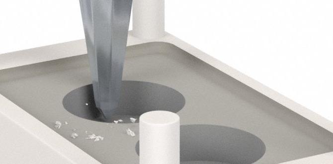
Machining Cast Iron with Your 1/8″ Carbide End Mill: A Step-by-Step Guide
Let’s walk through the process. We’ll assume you’re doing a simple pocketing operation or profiling an edge.
Step 1: Prepare Your Workpiece and Machine
- Secure the Workpiece: Mount your cast iron piece firmly in a vise or your machine’s table. Ensure it’s indicated in if precise alignment is needed.
- Insert the End Mill: Securely tighten your 1/8-inch carbide end mill in your machine’s collet or chuck. Ensure it’s properly seated and tight.
- Set Work Zero: Carefully establish your X, Y, and Z zero points on the workpiece. For Z zero, it’s common to touch off on the top surface of the cast iron.
- Set Up Toolpaths: Program your CNC machine or prepare your manual machine setup for the desired cuts.
Step 2: Set Cutting Parameters
Based on our earlier discussion:
- Spindle Speed: Start around 4,000-6,000 RPM.
- Feed Rate: Begin with a conservative feed rate, roughly 25-40 IPM, adjusting based on your spindle speed and desired chip load.
- Depth of Cut: For a 1/8-inch end mill in cast iron, take light axial depths of cut. A good starting point is 0.050″ to 0.100″ per pass. Radial depth of cut (how much width of the tool is engaged) should ideally be no more than 50% of the tool diameter (0.0625″) for pocketing, or less if possible (e.g., 0.030″) for a smoother finish and less load.
Step 3: Introduce Cutting Fluid/Air
Turn on your coolant mist, flood coolant, or air blast. Ensure the stream is directed at the cutting point of the end mill. Cast iron can create fine dust, so proper containment and evacuation are also important for your health and safety.
Step 4: The First Cut
Slowly engage the spindle to your set RPM. Then, begin feeding the end mill into the workpiece at your programmed feed rate. Make the first pass with a shallow depth of cut (e.g., 0.050″).
Observe and Listen:
- Sound: Is it a smooth whirring sound or a harsh chattering? Chattering indicates rigidity issues or incorrect speeds/feeds.
- Chips: Are the chips coming off cleanly and being evacuated? Small, powdery chips can mean you’re rubbing or feeding too slowly. Long, stringy chips are usually a sign of a softer material, not cast iron. Look for nice, curly chips.
- Heat: Is the area getting excessively hot? If so, increase coolant flow or reduce cutting speed.
Step 5: Make Subsequent Passes
Once you’ve completed the first pass and confirmed your parameters are working well, you can increase the depth of cut (if desired) for subsequent passes or continue with light passes to achieve the final dimensions. For pocketing, you’ll typically want to step down in Z incrementally and step over in X/Y until the pocket is complete. For profiling, you’ll be following the outer or inner contour of your part.
Step 6: Finishing Passes
For critical surfaces requiring excellent finish and tight tolerances, consider a light finishing pass. This is a pass where you take a very light depth of cut (e.g., 0.005″ – 0.010″) at a slightly increased feed rate (chip load per tooth) to clean up the surface. This smooths out any minor imperfections left by the roughing passes.
Step 7: Cool Down and Inspect
Once the machining is complete, let the spindle stop and allow the workpiece to cool slightly before removing it. Inspect the finished part for dimensional accuracy, surface finish, and any signs of chatter or tool breakage. If you’re happy with the results, great work!
Common Challenges and How to Solve Them
Even with the right tools and a solid plan, you might run into a few snags. Here’s how to troubleshoot.
Tool Breakage
This is the most frustrating. Reasons for a 1/8-inch end mill breaking:
- Too aggressive feed rate: You’re pushing too hard.
- Too deep of a cut: Especially axial depth.
- Workpiece movement: Not clamped securely.
- Tool runout: End mill not held properly in the collet or spindle.
- Entering the cut too fast: Plunging straight into material without ramping or a controlled entry.
- Chip recutting: Chips aren’t clearing properly.
Solution: Reduce feed rate, reduce depth of cut (both axial and radial), ensure rigid workholding, check tool runout, use a ramp entry into pockets, and improve chip evacuation.
Poor Surface Finish
If your surface finish isn’t up to par:
- Incorrect speeds or feeds: Usually feeding too fast or too slow, or running the spindle too fast.
- Tool wear: The end mill is dull.
- Chip recutting: Leading to small scratches.
- Machine rigidity: Vibration causing chatter.
Solution: Adjust feed rate and spindle speed (try slightly slower RPM and a moderate feed), use a fresh end mill, improve chip evacuation, ensure the machine and workpiece are rigid, and consider a dedicated finishing pass.
Overheating
If the tool or workpiece is getting too hot:
- Insufficient coolant: Not enough lubrication or cooling.
- Too high of spindle speed: Generating excess friction.
- Too slow of a feed rate: The tool is rubbing instead of cutting.
Solution: Increase coolant flow, reduce spindle speed, increase feed rate slightly (to achieve the correct chip load), or take lighter passes.
When to Consider an “Extra Long Shank” 1/8″ Carbide End Mill
You might think an “extra long shank” means you can cut deeper or reach further, and that’s true, but it comes with caveats. Here’s when it makes sense and when to be cautious:
Benefits of Extended Reach:
- Accessing Deep Pockets: The primary reason. It allows the cutting head of the end mill to reach areas that a standard length tool cannot.
- Machining Recesses: Useful for creating features or cleaning up surfaces within slightly deeper cavities.
- Avoiding Fixture Interference: If your workholding fixtures are positioned in a way that would collide with a standard-length tool.
Drawbacks and Precautions:
- Reduced Rigidity: The longer the overhang, the more the tool will deflect under cutting forces. This increases the risk of chatter, poor surface finish, and tool breakage.
- Increased Vibration: A longer, thinner tool is more prone to vibrating, especially at higher speeds or feed rates.
- Lower Cutting Parameters: You’ll almost certainly need to reduce your spindle speed, feed rate, and depth of cut compared to a standard-length end mill to maintain stability and tool life.
Recommendation: Only use an extra-long shank end mill if absolutely necessary for reach. If you can achieve the same result with a standard length, do so. If you must use one, be prepared to slow everything down and take lighter, more controlled passes