A 1/8″ carbide end mill is a precise tool perfect for detailed work on steel, especially when you need high material removal rates (MRR) with a 6mm shank and standard length. It’s ideal for intricate slots, pockets, and profiling in your steel projects.
Welcome to Lathe Hub! If you’ve ever looked at a piece of steel and thought, “How can I possibly cut this precisely?” you’re in the right place. Machining steel can seem intimidating, especially when you’re just starting out. One of the biggest challenges for beginners is selecting the right cutting tool. Today, we’re diving deep into a truly essential tool for anyone working with steel: the 1/8-inch carbide end mill. Don’t let its small size fool you; this little powerhouse is incredibly capable for detailed work. We’ll break down what makes it so special, how to use it safely and effectively, and why it’s your new best friend for steel projects in your home workshop. Get ready to gain the confidence to tackle those finer cuts!
What Exactly is a Carbide End Mill?
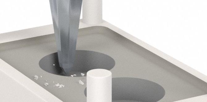
An end mill is a type of milling cutter. Think of it like a drill bit that can also cut sideways. Unlike a drill, which primarily cuts downwards into a material, an end mill can move in multiple directions – up, down, left, right, and even in circles. This versatility makes them indispensable for creating slots, pockets, profiles, and contours in various materials.
Now, what makes it “carbide”? Carbide, specifically tungsten carbide, is an extremely hard and wear-resistant material. This means carbide end mills can handle tougher materials like steel, cut at higher speeds, and last much longer than their counterparts made from High-Speed Steel (HSS). For machining steel, especially stainless steel, carbide is often the preferred choice due to its strength and ability to withstand the heat generated during cutting.
Why a 1/8″ Carbide End Mill for Steel?
You might wonder why such a small size, 1/8 inch (which is approximately 3.175mm, though commonly paired with a 6mm shank), is so important. Here’s the magic:
- Precision and Detail: That 1/8-inch diameter is perfect for creating narrow slots, small pockets, intricate internal corners, and fine detail work where larger tools simply won’t fit or would remove too much material. For tasks like engraving or creating very fine features on metal parts, this size is invaluable.
- Material Removal Rate (MRR) in Detail: While larger end mills handle bulk material removal faster, a 1/8″ carbide end mill, used correctly, offers a surprisingly high Metal Removal Rate for its size, especially in steel. This is achieved through proper speeds, feeds, and cutting strategies, allowing you to efficiently machine even tough alloys in tight spaces.
- Working with Stainless Steel: Stainless steel is notorious for being gummy and prone to work hardening, which means it gets harder the more you cut it. Carbide’s hardness and heat resistance are perfectly suited to combatting these challenges, allowing for cleaner cuts and preventing premature tool wear when machining stainless steel grades like 316.
- Common Shank Size: The 6mm shank is a very common size found on many CNC machines and even some manual milling attachments, making it readily compatible with a wide range of equipment. Standard length is key for predictable machining depths and avoiding chatter.
Understanding the Anatomy of a 1/8″ Carbide End Mill
Before we grab one, let’s understand what we’re looking at:
- Diameter: This is the cutting width of the end mill, 1/8 inch in our case.
- Number of Flutes: Flutes are the helical grooves that run up the cutting edge. For general steel machining with carbide, you’ll often see 2-flute or 4-flute end mills.
- 2-Flute: These have more chip clearance, which is excellent for softer metals and materials that produce longer, stringier chips, like aluminum. They are also good for plunging and slotting in steel.
- 4-Flute: These offer better surface finish and can handle higher feed rates in harder materials like steel because they provide more cutting edges and support. They are often preferred for finishing passes and general milling in steel.
- Shank: This is the part of the end mill that the collet or holder grips. A 6mm shank is standard for many smaller milling applications.
- Length: Standard length end mills offer a good balance of reach and rigidity. Extended or extra-long versions exist but can be more prone to vibration (chatter) if not used carefully.
- Coating: Some carbide end mills have special coatings (like TiN, TiCN, or AlTiN) that further enhance hardness, reduce friction, and improve performance in specific materials, especially steel. For steel, coatings like AlTiN (Aluminum Titanium Nitride) are excellent for high-temperature resistance.
Essential Tools and Setup for Using Your 1/8″ Carbide End Mill
The Milling Machine
While you can do some light milling with rotary tools with special attachments, a dedicated milling machine is ideal. For a 1/8-inch end mill, even a smaller benchtop CNC mill or a sturdy manual metalworking mill will work well. The key is rigidity. A wobbly machine will lead to poor cuts, tool breakage, and danger.
Collets and Holders
You’ll need a collet chuck or a set of collets that match the 6mm shank of your end mill and fit your milling machine’s spindle. A tight, runout-free grip is crucial for precision and tool life. A high-quality collet set ensures the end mill is held accurately.
Workholding
Securely holding your workpiece (the steel you’re cutting) is paramount. This could involve:
- Vise: A good machinist’s vise bolted firmly to the milling machine table is the most common method. Ensure the vise jaws are clean and provide a strong grip without deforming your part.
- Clamps: For larger or unusually shaped pieces, T-slot clamps can be used to hold the material directly to the machine table.
- Fixtures: For repetitive tasks, custom fixtures offer the best repeatability and accuracy.
Always ensure your work is clamped securely and there’s no chance of it shifting during the operation. A shifting workpiece can cause tool breakage, damage your machine, or worse, injury.
Measuring Tools
- Digital Caliper: Essential for measuring your stock, checking dimensions as you cut, and verifying tool diameter.
- Height Gauge or Depth Micrometer: For accurately setting the height of your end mill relative to your workpiece.
Safety Gear – Non-Negotiable!
This is the most important section. Never compromise on safety.
- Safety Glasses: Always wear ANSI approved safety glasses. A broken chip can travel at high speed. A full face shield over safety glasses is even better.
- Hearing Protection: Milling machines can be loud.
- Gloves (situational): While handling sharp tools or workpieces, cut-resistant gloves are a good idea. However, never wear loose-fitting gloves while the machine is running, as they can get caught and pull your hand into the machinery.
- Dust Mask/Respirator: Especially when machining certain metals, fine particulate matter is produced.
- Appropriate Clothing: Avoid loose clothing, dangling jewelry, or anything that could get caught in the machine. Tie back long hair.
Regarding machining safety, organizations like the Occupational Safety and Health Administration (OSHA) provide extensive guidelines for workshop safety. Familiarize yourself with their recommendations for machine operation. You can find general workplace safety guidelines on the OSHA website.
Step-by-Step: Using Your 1/8″ Carbide End Mill on Steel
Let’s walk through a typical operation. We’ll assume you’re making a slot in a piece of mild steel.
Step 1: Prepare Your Workpiece and Machine
Ensure your steel workpiece is clean, deburred, and securely clamped in your vise or on the milling table. Make sure the vise jaws are clean and the workpiece is seated firmly. Clean your milling machine table and ensure all controls are set to neutral or off.
Step 2: Select and Mount Your End Mill
Choose your 1/8-inch carbide end mill. If you’re slotting or doing a lot of plunge cutting in steel, a 2-flute might be suitable. For finishing or general milling, a 4-flute is often better. Insert the end mill into the appropriate collet, ensuring it’s fully seated. Tighten the collet nut within the chuck or holder, and then tighten this into your milling machine’s spindle. Ensure it’s secure and doesn’t wobble.
Step 3: Setting the Zero / Finding Your Work Origin
This is critical for accuracy. You need to tell the machine (or remind yourself on a manual machine) where your workpiece is in relation to the cutting tool.
- X and Y Axis: Using an edge finder or by carefully jogging the spindle until the side of the end mill just touches the edge of your workpiece, you can set your X and Y zero points. For example, if you want your slot centered, you’d find the center of your workpiece and set that as your X=0 and Y=0.
- Z Axis (Depth): This is the vertical zero. Carefully lower the spindle until the tip of the end mill just touches the top surface of your workpiece. This point is your Z=0. A piece of paper placed between the tool and workpiece can help you “feel” the moment of contact – when the paper can no longer move freely. Set your Z=0 at this point.
Step 4: Determine Cutting Parameters (Speeds and Feeds)
This is where things get specific and can be tricky for beginners. The optimal Spindle Speed (RPM) and Feed Rate (how fast the tool moves into the material) depend on:
- The type of steel (e.g., mild steel, stainless steel)
- The end mill’s diameter and number of flutes
- The machine’s rigidity
- Coolant or lubrication used
For a 1/8-inch carbide end mill in mild steel:
- Spindle Speed (RPM): A good starting point is often around 5,000-10,000 RPM. Carbide likes to spin faster than HSS.
- Feed Rate (IPM or mm/min): This is often the trickiest. For a 1/8″ end mill, you’re looking at chip loads in the range of 0.0005 to 0.002 inches per revolution (IPR). This translates to a feed rate calculated by: Feed Rate = RPM Chip Load Number of Flutes. For example, if RPM=7000, Chip Load=0.001 IPR, and Flutes=4, your feed rate would be about 7000 0.001 4 = 28 inches per minute (IPM).
Important Note on Stainless Steel: Stainless steel requires slower speeds and often a more aggressive feed to prevent work hardening. You might drop your RPM to 3,000-6,000 and adjust your feed rate accordingly. Always err on the side of caution, and use a good quality cutting fluid or mist system. For more detailed information on speeds and feeds for various materials, resources like the Machinery’s Handbook or online calculators from reputable tooling manufacturers can be invaluable. Be aware that Machinery’s Handbook is a professional reference tool, and interpreting its data for beginners may require guidance.
Step 5: Set Your Cutting Depths
Never try to cut the full depth of your slot in one pass, especially in steel. Make shallow cuts. For a 1/8-inch end mill:
- For Slotting: A Cut Depth of 0.030″ to 0.060″ (0.75mm to 1.5mm) per pass is a good starting point for mild steel. Steepen this for harder steels.
- For Profiling/Contouring: You might take shallower depth cuts.
You’ll set these depths in your CNC control or by carefully feeding the Z-axis down on a manual mill after setting your Z=0.
Step 6: Begin Cutting
Start the spindle at your chosen RPM.
Ensure coolant or cutting fluid is being applied effectively. If using a flood coolant system, turn it on. If using mist or manual application, apply frequently.
Begin feeding into the material at your calculated feed rate. Listen to the machine. A smooth whirring sound is good. A loud, chattering, or screeching sound indicates you need to adjust your speed, feed, or depth of cut. It might mean you’re feeding too fast, cutting too deep, or have runout.
Step 7: Conventional vs. Climb Milling
- Conventional Milling: The cutter rotates against the direction of feed. This is generally easier on the machine and tool, less likely to cause chatter, and better for beginners.
- Climb Milling: The cutter rotates in the same direction as the feed. This can provide a better surface finish and reduce cutting forces, but requires a rigid machine with no “backlash” in the feed screws, as it can quickly lead to tool breakage or damage if not set up perfectly. For beginners, stick to conventional milling for steel.
Step 8: Completing the Operation and Verification
Make incremental passes, raising your Z zero slightly after each pass if necessary, until you reach your desired final depth. After each pass, or when changing tools, it’s a good practice to clear chips from the workpiece and the flutes of the end mill. Use a brush or compressed air (wear eye protection!).
Once the operation is complete, turn off the spindle and then disengage the feed. Let the tool spin down before retracting it. Measure your machined feature (e.g., slot width and depth) with your calipers to ensure it meets your specifications.
Tips for Maximizing MRR with a 1/8″ End Mill in Steel
Achieving a good Material Removal Rate (MRR) with a small tool in tough material involves optimizing several factors:
- Chip Load: This is the thickness of the chip being removed by each flute. Increasing chip load (within tool limits) generally increases MRR. For a 1/8″ end mill, aim for the higher end of the recommended chip load range for your specific steel and tool.
- Cutting Fluid/Coolant: Absolutely essential for steel. It cools the cutting edge, lubricates the cut, and helps evacuate chips. Mist cooling or flood coolant systems are highly recommended.
- Tool Path Strategy: For slots, ensuring the end mill is fully engaged (conventional milling) at an appropriate depth of cut is key. For contouring, stepovers (sideways movement between passes) should be optimized. A smaller stepover will take more passes but give a better finish.
- Tool Material and Coating: As mentioned, carbide is king for steel. A good coating like AlTiN adds another layer of performance.
- Rigidity: Ensure your spindle, collet, tool holder, workpiece, and machine table are all as rigid as possible. Any flex will absorb cutting forces and reduce your effective MRR and tool life.
Carbide End Mill Types & Applications Comparison
While we’re focusing on the 1/8″ size for steel, it’s good to know about variations:
| End Mill Type | Typical Application (1/8″ Diameter) | Pros for Steel | Cons for Steel |
|---|---|---|---|
| 2-Flute Carbide | Slotting, pocketing, general milling in softer steels, general purpose. Good for chip evacuation. | Excellent chip clearance, good for plunging, less prone to clogging in stringy chips. | Can be noisier, may not provide as fine a surface finish as 4-flute, can chatter more easily in harder materials. |
| 4-Flute Carbide | Finishing passes, general milling in harder steels (stainless), creating finer surface finishes, higher MRR due to more cutting edges. | Better surface finish, higher rigidity, capable of higher feed rates in harder materials, more efficient in tough alloys. | Less chip clearance (can clog with gummy materials if not managed), requires more precise speed/feed settings, can be more prone to chatter if setup is not rigid. |
| Ball Nose Carbide | 3D contouring, creating radiused corners, fillets, mold making. | Essential for complex 3D shapes in steel. Surface finish can be excellent when
Related Posts |