Carbide end mills are excellent for dry cutting 1/8 inch copper. These specialized tools offer precision and speed without needing coolant, making them ideal for hobbyists and small workshops. Get ready to achieve clean, smooth cuts with minimal hassle.
Welcome to Lathe Hub! If you’re diving into working with copper, especially on your milling machine, you’ve likely encountered the need for the right cutting tools. Copper can be a bit tricky – it’s soft, which is great, but it can also gum up your tools quickly. That’s where a specific type of cutting tool, the 1/8 inch carbide end mill, comes into play, especially for dry cutting. We’re going to walk through exactly why this tool is a fantastic choice for copper and how to use it effectively. No complicated jargon here, just straightforward advice to get you cutting with confidence. Let’s get started!
Why a 1/8 Inch Carbide End Mill is Perfect for Copper
Copper is a popular material for hobbyist machinists and DIYers. It’s relatively soft, easy to shape, and has a beautiful finish. However, if you don’t use the right tools and techniques, it can lead to frustrating results. This is where the 1/8 inch carbide end mill shines, particularly when you’re looking to perform dry cuts.
The Magic of Carbide
Carbide, or tungsten carbide, is an incredibly hard ceramic compound. It’s significantly harder than high-speed steel (HSS), which is what many standard end mills are made from. This superior hardness means carbide tools:
Stay sharp longer: They can withstand more abrasion and maintain their cutting edge through tougher jobs.
Cut faster: Their hardness allows them to remove material more aggressively without overheating or deforming.
Handle higher temperatures: While we’re talking about dry cutting, even friction from dry cutting can generate heat. Carbide excels at dissipating this heat.
For a material like copper, which can be “gummy” and tend to stick to cutting tools, carbide’s durability and heat resistance are huge advantages.
The Charm of 1/8 Inch
The 1/8 inch (approximately 3.175 mm) diameter is a sweet spot for many precision tasks. This size is small enough for detailed work, intricate patterns, or engraving on copper. It allows for fine control and the ability to create delicate features that larger end mills simply can’t manage. When combined with the properties of carbide, a 1/8 inch end mill becomes a precise instrument for shaping copper.
The Beauty of Dry Cutting
Many machining operations, especially with softer metals like aluminum or copper, benefit from a lubricant or coolant to keep the cutting area cool, wash away chips, and extend tool life. However, for certain applications, dry cutting with the right tool can be perfectly acceptable and even preferable. This is especially true for hobbyists or those with smaller milling machines that might not be set up for flood coolant.
Why dry cutting works well with a carbide end mill for copper:
Simplicity: No mess from coolant. This makes setup and cleanup much faster and easier.
Cost-effectiveness: You don’t need to purchase or maintain coolant.
Material suitability: With proper speeds and feeds, a sharp carbide bit can manage the heat generated.
Chip evacuation: Good flute design on the end mill helps clear chips, preventing them from packing up.
Choosing Your 1/8 Inch Carbide End Mill for Copper
Not all 1/8 inch carbide end mills are created equal. For copper, you’ll want to consider a few key features to ensure optimal performance and tool life. Look for end mills specifically designed for non-ferrous metals or general-purpose use on softer materials.
Key Features to Look For:
Material: Tungsten Carbide, as discussed.
Number of Flutes: For copper, 2-flute or 3-flute end mills are generally recommended.
2-flute: Excellent for chip evacuation, which is crucial for gummy materials like copper. They provide more space for chips to exit, reducing the risk of clogging.
3-flute: Can offer a slightly better surface finish and can sometimes be run a bit faster than 2-flutes, but chip evacuation might be slightly less aggressive.
Avoid 4-flute end mills for most copper applications, as they can pack up with chips very easily and lead to tool breakage.
Coating: While not strictly necessary for dry cutting copper, some coatings can improve performance. AlTiN (Aluminum Titanium Nitride) or TiCN (Titanium Carbonitride) coatings are generally good all-around performers for various materials, including copper. However, for simple dry cutting, an uncoated carbide end mill will also perform well.
Helix Angle: A moderate helix angle (often around 30 degrees) is typical for general-purpose end mills and works well for copper. Very high helix angles are designed for aggressive material removal in softer materials but can be more prone to chatter.
Shank Diameter: Ensure the shank is the correct size for your collet or tool holder. For a 1/8 inch cutting diameter, you’ll most commonly find them with a 1/8 inch shank or a 1/4 inch shank. A 1/8 inch shank is typical for smaller CNC machines or manual mills where rigidity is a key concern for such a small tool. A common search term is “carbide end mill 1/8 inch 6mm shank standard length for copper dry cutting” which indicates a 1/8″ cutting diameter and a 6mm shank, a popular size in many modern machines.
Length: “Standard length” is usually sufficient. For very deep pockets, you might look for “long-reach” end mills, but these can be less rigid and more prone to vibration with such a small diameter.
Understanding Speeds and Feeds for Copper
This is arguably the most critical part of successful dry cutting with any end mill, especially a small carbide one. Too fast, and you’ll burn up the tool and melt the copper; too slow, and you’ll get a poor finish and chatter.
It’s important to understand that speeds and feeds are highly dependent on several factors:
The specific alloy of copper: Different copper alloys have varying hardness.
The rigidity of your machine: A wobbly mill will require slower, more conservative settings.
The depth of cut: How deep are you trying to mill?
The width of cut: How much material are you removing across the surface?
The specific end mill geometry.
However, for a 1/8 inch 2-flute carbide end mill working in standard copper (like C110 ETP or similar) for dry cutting, here are some general starting points. Always consult the end mill manufacturer’s recommendations if available.
Table 1: Recommended Starting Speeds and Feeds for 1/8″ Carbide End Mill in Copper (Dry Cutting)
| Parameter | Recommended Value | Notes |
| :——————– | :————————————- | :——————————————————————————————————— |
| Spindle Speed (RPM) | 10,000 – 20,000 RPM | Start at the lower end and increase if machining is smooth and chips are clear. Higher speeds increase heat. |
| Feed Rate (IPM) | 8 – 20 inches per minute (IPM) | This is the rate the tool moves through the material. Too slow causes rubbing and heat. Too fast causes chatter. |
| Chip Load (per tooth)| 0.001″ – 0.002″ | The thickness of the material removed by each cutting edge. This is derived from Feed Rate / (RPM Number of Flutes) |
| Axial Depth of Cut| 0.010″ – 0.030″ (0.25 mm – 0.75 mm) | How deep the end mill cuts into the material vertically. |
| Radial Depth of Cut| 0.010″ – 0.040″ (0.25 mm – 1 mm) | How far the end mill cuts into the material horizontally (e.g., for pocketing). Often a small percentage of the diameter. |
Understanding Chip Load:
Chip load is a crucial concept. It’s the thickness of the material each cutting edge removes.
Chip Load = Feed Rate / (Spindle Speed Number of Flutes)
If your chip load is too small, you get rubbing, which creates heat and a poor finish.
If your chip load is too high, you overload the cutting edge, leading to chatter, tool breakage, or poor chip evacuation.
For 1/8 inch carbide end mills in copper, a chip load between 0.001″ and 0.002″ is a good target.
Example Calculation:
Let’s say you have a 2-flute end mill, you’re running at 15,000 RPM, and you want a chip load of 0.0015″.
Your Feed Rate would be: 15,000 RPM 2 flutes 0.0015″ chip load = 45 IPM.
Important Note: These are starting points. Always listen to your machine and your tool. Observe the chips:
Powdery chips or smoke: You’re likely running too hot (too fast spindle, too slow feed, too much friction). Slow down, increase feed rate slightly, or reduce cut depth.
Long, stringy chips: May indicate you’re rubbing or the feed rate is too high for the spindle speed.
Small, crunchy chips: Usually a good sign of efficient cutting.
Chatter or vibration: Reduce feed rate, shallow the cut depth (axial/radial), or ensure your workpiece is fixtured securely.
For more information on calculating speeds and feeds, you can refer to resources like the Machinery’s Handbook or online calculators, but always adapt them to your specific setup. Remember that CNC machines often have feed rate override controls that allow you to adjust on the fly.
Setting Up Your Workpiece and Machine
Proper setup is as vital as having the right tool. Even the best end mill will struggle if your workpiece is loose or your machine isn’t dialed in.
Secure Fixturing is Non-Negotiable:
Your copper workpiece must be held down rigidly. Any movement will result in inaccurate cuts, tool damage, or dangerous situations.
Vise: A good quality milling vise is ideal. Ensure the vise jaws are clean and the workpiece is seated firmly. Use soft jaws if you’re concerned about marking the copper.
Clamps: If you don’t have a vise, use milling clamps (like T-slot clamps) to secure the copper to the milling table. Ensure all clamping screws are tight.
Double-sided Tape: For very thin or small pieces, strong double-sided milling tape can sometimes work, especially on a sacrificial sub-plate, but it’s generally less secure for anything other than very light cuts.
Machine Preparation:
Clean the Spindle and Collet: Ensure the spindle taper and your collet are free of debris. A clean connection ensures true running and prevents runout, which can cause the end mill to cut inconsistently.
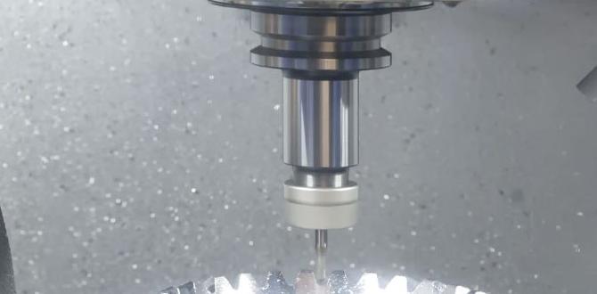
Install the End Mill Correctly: Insert the end mill into the collet and tighten it securely. Make sure enough of the shank is gripped by the collet for rigidity – generally, at least half the cutting length should be supported if possible, though this often can’t be achieved with small ER collets. Ensure the end mill is centered.
Set Your Zero Point (Work Offset): Accurately define your X, Y, and Z zero points. For Z zero, it’s common to use a Z-axis probe, a touch-off plate, or carefully lower the end mill until it just kisses the surface of the workpiece (using paper between the tool and work is a common method).
Performing the Dry Cut: Step-by-Step Guide
Now that you have your tool, your settings, and your workpiece ready, let’s get cutting. This guide assumes you are using a CNC mill, but the principles apply to manual mills as well.
Step 1: Load Your Program (CNC) or Set Up Your Manual Operation
CNC: Load your G-code program into the machine controller. Double-check your speeds and feeds within the program.
Manual: Set up your desired cuts using the machine’s handwheels.
Step 2: Dry Run Your Program (CNC Recommended!)
Before cutting expensive material, perform a “dry run.” This means running the program with the spindle OFF or at a very low RPM with no engagement into the material. Watch the toolpath on your screen or observe the machine’s movements in the air to ensure everything is as expected and there are no crashes.
Step 3: Initial Z-Touch-Off
As mentioned in setup, accurately set your Z-zero. This tells the machine where the top surface of your material is.
Step 4: Begin the Cut (Start Slowly!)
CNC: Start the spindle up to your target RPM. Engage the feed rate. It’s a good idea to start with the feed rate override at a lower percentage (e.g., 20-50%) and gradually increase it to your programmed feed rate while listening to cutting sounds.
Manual: Begin your cut at a deliberate pace.
Step 5: Monitor the Cutting Process
This is where your observation skills come in:
Listen to the Sound: A smooth, consistent whirring or hashing sound is good. Loud grinding, squealing, or irregular noises indicate problems.
Watch the Chips: Are they forming well? Are they being ejected cleanly? Is there any sign of melting or gumming up?
Feel for Vibration: Excessive vibration (chatter) means something is wrong.
Observe for Smoke: A little bit of smoke from friction is sometimes unavoidable in dry cutting, but copious amounts mean you’re overheating.
Step 6: Adjust as Needed
If things sound bad or you see excessive heat: Reduce the feed rate override immediately. If the issue persists, stop the machine and review your speeds and feeds, depth of cut, or fixture rigidity.
If cutting smoothly: Gradually increase the feed rate (if you started low) up to your target.
Step 7: Completing the Operation
Let the program finish or complete your manual passes. Once the tool is clear of the material, stop the spindle.
Step 8: Inspect and Clean Up
Carefully remove the workpiece.
Inspect the cut quality. It should be clean and relatively smooth.
Brush away any chips and dust from the machine.
Clean your workpiece and inspect the end mill for any signs of wear or damage.
Common Issues and How to Solve Them
Even with the best intentions, you might run into a few snags when dry cutting copper. Here’s how to tackle them:
Issue 1: Gumming Up / Chip Welding
Cause: Copper is soft and can “weld” itself to the cutting edges of dull or incorrectly used end mills. This is exacerbated by heat.
Solution:
Increase Feed Rate Slightly: This creates a larger chip load, which can help push the material away before it sticks.
Reduce Spindle Speed Slightly: This reduces heat generation.
Shallow Your Cut: Reduce axial and/or radial depth of cut.
Ensure Sharp Tool: A dull tool will always have this problem. If the end mill is not cutting cleanly, it’s time for a new one.
Consider a Tiny Amount of Lubricant: If dry cutting is proving impossible, even a tiny drop of cutting oil (applied strategically, not flooded) or a specialized aluminum/copper cutting lubricant can make a huge difference. Look for lubricants specifically designed for soft, gummy metals.
Issue 2: Chatter / Vibration
Cause: This is often due to a lack of rigidity somewhere in the system: a loose workpiece, a poorly supported end mill, excessive depth of cut, or a machine with play in its axes.
Solution:
Check Fixturing: Ensure the workpiece is clamped down rock solid.
Reduce Depth of Cut: Take shallower passes axially and radially.
Reduce Feed Rate: A slower feed rate can sometimes dampen vibrations.
Increase Spindle Speed (Carefully): Sometimes, moving into a different harmonic frequency can help, but this can also increase heat.
Ensure Proper Tool Stick-out: As short as possible.
Machine Maintenance: Ensure your machine’s ways and gibs are properly adjusted for a rigid cut.
Issue 3: Burning or Melting of Copper
Cause: Excessive heat generated by too much friction. This happens with too slow a spindle speed, too fast a feed rate, or too much rubbing contact.
Solution:
Increase Spindle Speed: Get the tool spinning faster to slice through the material, rather than rubbing it.
Decrease Feed Rate: Slow down how fast the tool moves through the material.
Reduce Depth of Cut: Remove less material per pass.
Check for Dullness: A dull tool creates more friction.
Issue 4: Poor Surface Finish
Cause: A combination of factors including incorrect speeds/feeds, tool wear, vibration, or improper tool path strategy.
Solution:
* Refine Speeds and Feeds: Aim for the optimal chip load.


