A 1/8 inch, 6mm shank reduced neck carbide end mill is the ideal tool for machining heat-resistant cast iron due to its strength, heat resistance, and precise cutting geometry, ensuring clean cuts and preventing tool breakage.
Welcome to Lathe Hub! Ever stared at a piece of metal and wondered how to shape it perfectly? Or perhaps you’ve admired finely crafted wooden pieces and thought, “How did they do that?” You’re in the right place! Mastering tools like metal lathes, milling machines, and wood lathes can seem daunting at first. With so many bits and pieces, settings, and techniques, it’s easy to feel overwhelmed. But don’t worry, that’s exactly why I’m here. My goal is to break down these incredible machines and their accessories, like the specialized carbide end mill we’ll discuss, into simple, manageable steps. We’ll explore how to use them safely and effectively, turning your workshop dreams into reality. Get ready to learn, build confidence, and create amazing projects!
Choosing the Right End Mill for Tough Materials: A Beginner’s Guide
When you’re starting out with machining, especially with tougher materials like cast iron, picking the right cutting tool is crucial. It’s not just about having a tool; it’s about having the correct tool for the job. This is where specialized end mills, like the “carbide end mill 1/8 inch 6mm shank reduced neck for cast iron heat resistant,” come into play. You might see these specs and think, “That’s a mouthful!” But each part tells us something vital about its performance. We’ll delve into what each of those terms means and why they make this specific end mill a workhorse for dealing with challenging materials.
Understanding the Anatomy of Your End Mill
Let’s break down that technical name piece by piece so you know exactly what you’re looking at and why it matters, especially for beginners.
Carbide: The Super Material
What it is: Carbide, also known as tungsten carbide, is a composite material made from tungsten carbide powder and a binder, typically cobalt.
Why it’s great for machining: It’s incredibly hard, even harder than high-speed steel (HSS). This hardness means it can cut through tough materials and maintain its sharp edge for much longer. It also holds up well at high temperatures that are generated during machining.
What it means for you: Using a carbide end mill versus a steel one on cast iron means you’ll get cleaner cuts, less tool wear, and you can often work at faster speeds, making your job easier and more efficient.
End Mill: The Cutting Tool
What it is: An end mill is a type of milling cutter that has cutting edges on its outer diameter and in its center. They are used in milling machines to cut grooves, slots, pockets, and contours in a workpiece.
Why it’s important: Unlike a drill bit that drills straight down, an end mill can cut sideways and plunge into material, giving you much more versatility for shaping and profiling.
1/8 inch (Diameter): Precision Matters
What it is: This refers to the diameter of the cutting portion of the end mill. So, 1/8 inch is a very small, precise diameter.
Why it’s useful: Smaller diameter end mills are perfect for detailed work, creating fine details, small slots, or machining in tight spaces. For beginners, this size can be forgiving for smaller projects.
6mm Shank: The Connection Point
What it is: The shank is the smooth, un-fluted part of the end mill that fits into the collet or tool holder of your milling machine. In this case, it’s 6mm, which is approximately 1/4 inch. This size is common for smaller machines, especially those used in hobbyist workshops or for lighter-duty milling.
Why it matters: You need to ensure your milling machine’s collet or chuck can accept a 6mm shank. Many smaller import machines, especially benchtop models, are designed with metric collets, making a 6mm shank a perfect fit.
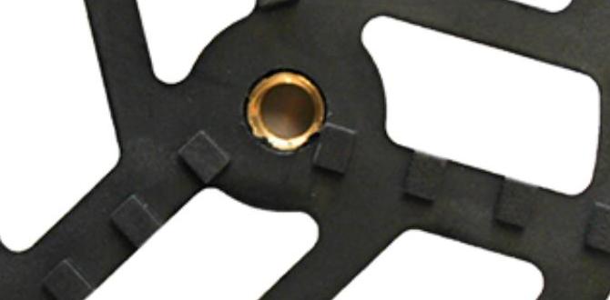
Reduced Neck: The Smart Design
What it is: The “reduced neck” means that there’s a part of the end mill, just above the cutting flutes, that is slightly thinner than the cutting diameter.
Why it’s a benefit: This feature is designed to help prevent the end mill from rubbing against the walls of a slot or hole it has just cut. In deep slots or channels, a standard end mill might have its flutes rubbing against the sides, causing excessive heat and wear. The reduced neck allows for slightly more clearance, extending the life of the tool and improving the finish of your workpiece.
For Cast Iron: The Target Material
What it is: Cast iron is a versatile alloy of iron, carbon, and silicon. It’s known for its good castability, wear resistance, and vibration damping properties. However, it can also be abrasive and brittle, making it a challenging material to machine.
Why this end mill is good for it: Standard end mills might struggle, chipping easily or wearing out fast. The specific design of this carbide end mill, combined with its material, is optimized to handle cast iron’s toughness and abrasiveness.
Heat Resistant: Staying Cool Under Pressure
What it is: This indicates the material and geometry of the end mill are designed to withstand the high temperatures generated during machining without losing their hardness or structural integrity.
Why it’s crucial: Machining tough metals like cast iron generates significant heat. If your tool can’t handle that heat, it will dull quickly, break, or even melt. A heat-resistant end mill ensures a more stable cutting process and a longer tool life.
Combining all these elements, the “carbide end mill 1/8 inch 6mm shank reduced neck for cast iron heat resistant” is a precision tool built to tackle the demanding task of milling into cast iron with durability and accuracy.
Why Use This Specific End Mill for Cast Iron?
Cast iron isn’t like soft aluminum or easy-to-cut plastic. It’s strong, can be brittle, and it’s abrasive. Trying to cut it with the wrong tool is a recipe for frustration. Here’s why our specialized end mill shines:
Durability: Carbide is significantly harder than steel alloys. This means it can stand up to the abrasive nature of cast iron without easily chipping or wearing down.
Heat Management: Machining creates friction, and friction creates heat. Cast iron generates a lot of heat. A heat-resistant carbide end mill (often called a high-performance end mill) keeps its hardness and cutting ability even when things get hot. This prevents ‘chip welding’—where chips stick to the tool—and premature tool failure.
Precision: The 1/8-inch diameter allows for fine details and tight tolerances, which are often needed in machining cast iron parts. The 6mm shank is a common size for smaller milling machines, making it accessible for home workshops.
Reduced Neck Advantage: As mentioned, the reduced neck is a clever design for deeper cuts or when working in narrow slots. It minimizes the risk of the tool body dragging, which can happen with standard end mills, saving the tool and improving the surface finish.
Think of it this way: you wouldn’t use a butter knife to chop down a tree. Similarly, you wouldn’t use a cheap, unhardened steel bit for serious cast iron work. This carbide end mill is the right “tool for the job” designed for the specific challenges of cast iron.
Getting Started with Your Milling Machine: Essential Setup
Before you even think about cutting, you need to set up your milling machine correctly. Safety and precision start here.
Essential Milling Machine Components for End Milling
Let’s identify the key parts you’ll interact with when using an end mill:
Spindle: The part of the machine that rotates the cutting tool.
Collet Chuck or Tool Holder: This is what holds the end mill’s shank securely in the spindle. You’ll need a collet that matches your 6mm shank end mill.
Collets: These are sleeves that fit into the collet chuck. They have tapered interiors and exteriors. When you tighten the collet nut, it clamps down on the end mill shank, holding it firmly.
Workholding Device: This is how you secure your workpiece to the milling machine table (e.g., vise, clamps).
Milling Machine Table: The surface where you mount your workholding device. It moves horizontally (X-axis) and vertically (Y-axis) to position the workpiece relative to the cutter.
Z-Axis Control: This controls the vertical movement of the spindle and thus the depth of cut.
Selecting and Installing Your End Mill
1. Choose the Right Collet: Ensure you have a 6mm collet for your collet chuck. If your machine has an R8 spindle (common on many benchtop mills), you’ll need an R8 collet chuck with a 6mm collet.
2. Clean Everything: Make sure the collet, collet chuck, and the end mill shank are perfectly clean. Any dirt, oil, or chips can cause the tool to be held off-center, leading to runout, vibration, and poor cutting.
3. Loosen the Collet: Unscrew the collet nut on your collet chuck. Place the collet into the chuck, ensuring it seats properly.
4. Insert the End Mill: Carefully slide the 6mm shank of your end mill into the collet. Ensure it’s inserted deeply enough to be held securely by the collet, but not so deep that the flutes disappear into the collet. The reduced neck area should typically be within the collet.
5. Tighten the Collet: Hand-tighten the collet nut first. Then, using the appropriate wrench, tighten it firmly. Don’t overtighten, as this can damage the collet or the tool, but it needs to be snug enough to prevent the tool from slipping under cutting forces.
6. Check for Runout (Optional but Recommended): If you have a dial indicator, you can check for runout by placing the indicator on the end mill shank or body and rotating the spindle slowly by hand. Ideally, you want very little wobble (runout).
Workpiece Setup: Securing Your Material Safely and Firmly
This step is absolutely critical. If your workpiece isn’t held securely, it can move during machining, leading to ruined parts, damaged tools, or even causing an accident.
Choosing the Right Workholding Method
For beginners, a milling vise is usually the easiest and safest option.
Milling Vise: This is a heavy-duty vise designed for machining. It has hardened jaws and is built to withstand significant cutting forces.
How to use it:
1. Mount the Vise: Securely bolt the milling vise to the table of your milling machine. Use the T-slots on the table and the base of the vise.
2. Position the Workpiece: Place your block of cast iron (or whatever you’re machining) into the vise jaws. Ensure it’s seated firmly against the fixed jaw.
3. Clamp Down: Slowly and evenly tighten the vise handle. You want it snug, but don’t crank it down so hard that you warp the workpiece or put excessive stress on your machine. It should feel solid and unmoving.
4. Check Alignment: Use a machinist’s square to ensure the vise jaws are square to the table’s travel. Also, check that the workpiece itself is seated squarely.
Clamping Directly to the Table: For larger or irregularly shaped parts, you might need to use clamps directly on the table. This requires more knowledge of clamping techniques and proper use of T-nuts and studs. For beginners, stick to a vise.
Introducing Basic Milling Operations: Facing and Pocketing
With your end mill installed and your workpiece secured, you’re ready to make some chips! For beginners, two common operations you might perform with an end mill are facing and pocketing.
Facing: Creating a Flat Surface
Facing means removing material from the top surface of your workpiece to make it perfectly flat and to bring it to a specific thickness.
Tools You Might Need:
Your milling machine
Carbide end mill (1/8 inch, 6mm shank, reduced neck for cast iron heat resistant)
Milling vise
Your cast iron workpiece
Safety glasses and ear protection
Chip brush or vacuum
Machinist’s square
Dial indicator (optional, for accuracy)
Step-by-Step Facing Procedure:
1. Set Up Your Machine: Ensure your end mill and workpiece are secured as described above.
2. Set Your Zero Point (X and Y): Carefully bring the rotating end mill down to touch the surface of your workpiece at a desired starting point (usually a corner). Use a piece of paper or a gentle touch to find where the cutter just “kisses” the surface. This is often referred to as “finding Z=0”. You’ll then set your machine’s DRO (Digital Readout) or your machine’s axis to zero at this point relative to the workpiece.
3. Set Your Cutting Depth (Z): Most machines have a way to control the depth of cut (Z-axis). You’ll want to plunge the end mill to the desired depth for your first pass. For facing, you’re moving the cutter across the surface, not plunging into it deeply. So, this step is about setting how much material you want to remove from the top.
4. Engagem the Spindle at Correct Speed: Turn on your milling machine’s spindle. The speed (RPM) depends on the material, the end mill diameter, and the type of carbide. For cast iron and a 1/8 inch end mill, a slower speed is generally safer for beginners, perhaps around 500-1000 RPM. A good starting point for carbide on cast iron is often around 200-400 surface feet per minute (SFM). For a 1/8″ (0.125″) tool, this translates to roughly:
SFM = (Diameter π RPM) / 12
RPM = (SFM 12) / (Diameter π)
RPM = (300 12) / (0.125 3.14159) ≈ 9165 RPM. This is very high and unrealistic for a small home shop mill. More realistically, for a 1/8″ carbide tool on cast iron on a small mill, you might be in the 500-1500 RPM range. It’s better to be conservative.
Note: Consult the end mill manufacturer’s recommendations if available!
5. Set Your Feed Rate: This is how fast the table moves the workpiece into the cutter. For cast iron, a moderate feed rate is good. You want to hear a consistent cutting sound, not chattering (too fast) or rubbing (too slow). For a 1/8″ end mill, a feed rate of around 0.001 to 0.003 inches per tooth (IPT) is a reasonable starting point. If your end mill has 4 flutes, this would be a table feed of 0.004 to 0.012 inches per minute (IPM). Again, this is very slow. A more practical feed rate might be 5-15 IPM for a small mill.
Feed Rate = Number of Flutes IPT RPM
Using 1000 RPM and an IPT of 0.002: 4 flutes 0.002 IPT 1000 RPM = 8 IPM.
6. Make Your First Pass: Slowly engage the feed, moving the table to feed the workpiece under the spinning end mill. Let the end mill pass across the entire surface.
7. Clean and Inspect: After the pass, disengage the feed, lift the spindle out of the cut, and stop the spindle. Brush away chips. Inspect the surface. Is it flat? Have you removed enough material?
8. Repeat if Necessary: Continue making passes, adjusting the depth of cut or table movement slightly for each pass until your surface is flat and at the desired thickness. You may need to take shallow passes repeatedly to achieve a good finish.
Pocketing: Creating a Recessed Area
Pocketing involves milling out a depression or cavity within the surface of your workpiece.
Step-by-Step Pocketing Procedure:
1. Define the Pocket Area: Mark out or set up your workpiece so the boundaries of the pocket are clearly defined.
2. Set Your Zero Point: Similar to facing, find your “go-to” start point for the pocket, often a corner, and set your X, Y, and Z zeros.
3. Plunge the End Mill (Carefully!): You need to get the end mill down into the material to start removing it. The 1/8 inch end mill has a 6mm shank, and a reduced neck. This means it’s less rigid than a larger end mill.
Plunge Feed Rate: Use a much slower feed rate for plunging than for horizontal cutting. Typically, around 1/3 to 1/2 the normal feed rate. This prevents shock loading the end mill.
Plunge Depth: Don’t plunge the entire depth of your pocket in one go. Take shallow plunges, e.g., 1/8 inch (or less) at a time, retracting the tool fully between plunges if necessary, especially in harder materials.
4. Begin Cutting the Pocket Walls: Once the end mill is at the required depth, start feeding horizontally to mill out the pocket.
* Stepover: This is the distance the end mill moves sideways (