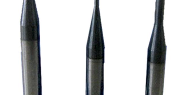
Carbide end mill 3/16 inch machining copper precisely is achievable and highly effective for intricate designs and clean cuts with the right approach.
Working with metal can seem daunting, especially when you’re just starting out. Copper, with its beautiful luster and conductivity, is a fantastic material for many DIY and professional projects. But getting those clean, precise cuts can be tricky. You might have heard about using a 3/16 inch carbide end mill for copper and wondered if it’s really the best way. Well, I’m here to tell you that with the right knowledge and tools, machining copper with this specific end mill can be a real game-changer. It’s all about understanding the bits and pieces of the process to get those genius results every time. Let’s dive in and make this machining task simple and successful!
Carbide End Mill 3/16 Inch: Your Secret Weapon for Brilliant Copper Machining
When you’re looking to achieve precise and beautiful results when machining copper, the right tooling makes all the difference. For hobbyists and emerging machinists, the 3/16 inch carbide end mill has emerged as a surprisingly effective tool, especially for tackling this relatively soft but sometimes stubborn metal. It’s not just about having a tool; it’s about understanding how to leverage its strengths for tasks like creating intricate designs, detailed circuitry patterns, or even functional components.
Copper, while not as hard as steel, has properties that can cause challenges. It can be gummy, meaning it tends to stick to cutting tools rather than cleanly shearing away. This can lead to poor surface finishes, tool loading (where chips build up on the cutting edge), and premature tool wear. However, a well-chosen carbide end mill, specifically one designed for or well-suited to softer metals like copper, can overcome these hurdles.
This guide is for you, the beginner machinist, the DIY enthusiast, or the curious woodworker dipping your toes into metalworking. We’ll break down why a 3/16 inch carbide end mill is a smart choice for copper, what specific features to look for, and how to use it safely and effectively. We’ll cover everything from selecting the right end mill to setting up your milling machine and achieving that perfect, shiny copper finish.
Why a 3/16 Inch Carbide End Mill for Copper?
You might be wondering why a 3/16 inch size and why carbide? It’s a combination that offers a sweet spot for many common copper machining tasks.
Size Matters: A 3/16 inch (0.1875 inches) end mill is a versatile size for many applications. It’s small enough to create detailed features, fine lines, and intricate patterns often found in decorative pieces, electronic components, or model making. It’s not so small that it becomes fragile, nor so large that it requires an extremely powerful machine or massive depths of cut. This size allows for good control and the ability to get into tighter spaces.
Carbide’s Edge: Carbide (tungsten carbide) is a man-made, extremely hard material. This hardness offers several advantages over traditional High-Speed Steel (HSS) end mills:
Heat Resistance: Carbide can withstand much higher operating temperatures. While copper machining won’t hit steel levels of heat, carbide’s ability to stay hard at elevated temperatures means it can maintain its cutting edge longer and at faster speeds.
Wear Resistance: Its extreme hardness makes it highly resistant to wear. This means it holds its sharp edge longer, providing more consistent cuts over its lifespan, which is crucial for achieving repeatable, high-quality results.
Rigidity: Carbide is also a more rigid material than HSS, which contributes to less deflection during cutting. This rigidity is key for maintaining dimensional accuracy in your parts.
When machining copper, the goal is to shear the material cleanly without dragging or gumming up the tool. Carbide’s hardness and ability to maintain a sharp edge make it ideal for this.
Specific Features to Look For: The “Extra Long” Advantage
While any carbide end mill can cut copper, certain types are optimized for it, and specific design features can significantly enhance your results. For “genius copper machining,” consider these points. The keyword mentions “extra long” – let’s explore why that’s relevant.
Number of Flutes: For softer metals like copper, you generally want fewer flutes.
2-Flute End Mills: These are often the go-to for softer, “gummy” materials like aluminum and copper. The increased space between the cutting edges (gullets) allows chips to evacuate more freely. This reduces the tendency for the material to clog the flutes, which is a common problem with copper.
3-Flute End Mills: Can sometimes be used for copper, especially for finishing passes or if the material is less gummy. They offer a better surface finish than 2-flutes but have less chip clearance.
4-Flute End Mills: Generally not recommended for soft coppers as they are more prone to loading.
Helix Angle:
Low Helix Angle (e.g., 15-30 degrees): These are excellent for soft, ductile materials like copper. A lower helix angle means the cutting edges engage the material more gradually, reducing chatter and promoting a smoother cut. It also helps with chip evacuation.
High Helix Angle (e.g., 45-60 degrees): Better for harder materials or for achieving a smoother finish, but can be more prone to chatter and chip packing in gummy materials.
Coatings: Some specialized coatings can improve performance on specific materials. For copper, a ZrN (Zirconium Nitride) coating is often beneficial. It’s gold-colored and provides a low friction surface, which helps prevent material buildup (welding) on the cutting edge, improving tool life and surface finish.
“Extra Long” Shank: The term “extra long” in the context of an end mill usually refers to the length of the tool’s shank (the part that goes into the collet or holder) or the overall length of the tool body.
Longer Reach: An “extra long” end mill typically has a longer reach from the collet to the cutting edges. This is crucial for reaching into deeper pockets, undercuts, or complex geometries without the need for specialized holders or extensions. For copper, a longer reach allows for more flexibility in part design and machining strategies.
Rigidity Considerations: While a longer reach offers access, it also introduces potential for increased deflection due to reduced rigidity. This is where the carbide material becomes even more important, as it’s inherently more rigid than HSS. You’ll need to compensate with lighter depths of cut and feed rates when using longer tools.
“High MRR” Capability: This refers to High Material Removal Rate. This is achieved through a combination of factors: appropriate flute design, helix angle, material of the end mill, and importantly, optimized cutting parameters (speed and feed). An end mill designed for high MRR will have chip-breaker features or geometries that allow for aggressive material removal without overloading the tool. For copper, a 2-flute end mill with good chip evacuation and suitable cutting speeds can achieve high MRR.
So, a 3/16 inch, 2-flute, low-helix carbide end mill, perhaps with a specific coating and an extended reach, is a fantastic candidate for “genius copper machining.”
Setting Up for Success: Your Milling Machine and Workpiece
Before you even think about touching the copper with your end mill, a solid setup is vital. This is where many beginner frustrations start, so let’s get it right.
1. Securing Your Workpiece
Copper is relatively soft, so it needs to be held firmly and without distortion.
Vise: A good quality milling vise is your best friend. Ensure the vise jaws are clean and that you have a firm grip on the copper. You might consider using soft jaws (made of aluminum or plastic) if your copper piece is delicate or has a finely finished surface you don’t want to mar.
Clamps: For larger or irregularly shaped pieces, several sturdy clamps can be used. Ensure they are placed to provide even pressure and support the workpiece against the cutting forces. Always clamp on solid areas, not overhangs.
Double-Sided Tape (Specialized): For very thin copper sheets, some advanced users employ strong, specialized double-sided tapes to hold the workpiece to a sacrificial fixture or the machine table for intricate engraving work. However, for general machining, a vise or clamps are more common and reliable.
2. Machine Considerations
Rigidity: Ensure your milling machine is stable and rigid. Any play or wobble in the machine will be amplified during the cut, especially with a long end mill.
Spindle Speed (RPM): Copper machining requires specific speeds. Too fast, and you’ll generate excessive heat and friction, leading to gumming and tool wear. Too slow, and you might not get an efficient cut. We’ll cover recommended speeds later.
Coolant/Lubrication: While you can dry machine some coppers, using a coolant or lubricant is highly recommended. It helps to:
Cool the cutting zone: Reduces heat buildup.
Lubricate the cut: Prevents material from welding to the tool.
Flush chips away: Improves chip evacuation.
For copper, a light oil, cutting fluid, or even a mist coolant works well. Avoid water-based coolants that can cause copper to oxidize rapidly if not dried properly.
3. Tool Holder and Collet
Collet Chuck: Using a high-quality collet chuck (e.g., ER collet system) is generally superior to a standard drill chuck for holding end mills. Collet chucks offer better runout (how perfectly the tool spins) and a more secure grip, which is essential for precision machining and to prevent chatter. Ensure your collet is the correct size for the 3/16 inch shank.
Runout: Minimize runout. If the end mill doesn’t spin perfectly true, one side will cut deeper than the other, leading to poor finish, increased tool wear, and potential tool breakage.
Step-by-Step: Machining Copper with Your 3/16 Inch Carbide End Mill
Now that your setup is ready, let’s walk through the process of machining copper. This guide focuses on achieving a good finish and avoiding common pitfalls.
Step 1: Select Your End Mill (Recap)
Based on our earlier discussion, aim for a 3/16 inch, 2-flute carbide end mill with a low helix angle (around 20-30 degrees). A ZrN coating is a bonus. If you have an “extra long” one, remember to use lighter passes.
Step 2: Calculate Cutting Parameters (Speeds and Feeds)
This is where the “genius” part really starts to shine. Incorrect speeds and feeds are the biggest cause of problems.
Surface Speed (SFM or SMM): This is the speed at which the cutting edge moves across the material. For copper and carbide, a good starting point for surface speed is often between 200-400 SFM (Surface Feet per Minute). Let’s convert this to RPM for a 3/16 inch end mill.
The formula is: RPM = (SFM 3.25) / Diameter (inches)
For 3/16 inch (0.1875 inches) and a target of 300 SFM:
RPM = (300 3.25) / 0.1875 = 5200 RPM.
Note: This is a starting point. You may run this higher or lower depending on your specific copper alloy, machine rigidity, and coolant.
Feed Rate (IPT or IPR): This is how fast the tool advances into the material. For a 3/16 inch, 2-flute end mill in copper, a good starting point for Inch Per Tooth (IPT) is around 0.001 to 0.003 inches per tooth.
The formula for IPM (Inches Per Minute) is: IPM = IPT Number of Flutes RPM
Using our example of 5200 RPM and aiming for 0.002 IPT:
IPM = 0.002 2 5200 = 20.8 IPM.
This is a very light feed rate, which is good for starting out. You might be able to increase this as you gain confidence.
Table: Recommended Starting Cutting Parameters for 3/16″ Carbide End Mill in Copper
| Parameter | Value (Approximate) | Notes |
| :—————- | :—————— | :———————————————————– |
| Material | Copper | (e.g., C110, C101) |
| Tool Type | 3/16″ Carbide 2-Flute | Low helix, coated optional |
| Surface Speed | 200-400 SFM | Start lower and adjust. |
| Spindle Speed (RPM) | 3500-7000 RPM | ~5200 RPM for 300 SFM. Adjust for tool length and rigidity. |
| Chip Load (IPT) | 0.001-0.003″ | Feel the cut; adjust based on sound and chips. |
| Feed Rate (IPM) | 10-40 IPM | ~20-25 IPM for initial tests. |
| Depth of Cut (Axial) | 0.010″ – 0.050″ | Very light for finishing, up to 0.1x diameter for roughing. |
| Width of Cut (Radial) | 25% – 75% D | 50% typical. Climb milling preferred. |
Depth of Cut (Axial and Radial):
Axial Depth of Cut (DOC): How deep the end mill cuts into the material along its axis. For finishing passes, this should be very shallow (e.g., 0.010 inches). For roughing, you can go deeper, but for copper and especially with an extra-long end mill, keep it moderate (e.g., 0.050 inches or less). A common rule of thumb for rigid setups is to keep axial DOC to 0.5x diameter or less.
Radial Depth of Cut: How much of the end mill’s diameter engages the material side-on. For pocketing, you might use 50% of the diameter. For slotting, this would be 100%. For 3/16 inch, using 50% means cutting with about 0.09375 inches of the tool’s side.
Climb Milling vs. Conventional Milling:
Climb Milling (Down Milling): The tool rotates in the same direction as it feeds into the workpiece. This is generally preferred for machining softer metals like copper because the chips are thicker at the start of the cut and thinner at the end. This results in a better surface finish and reduces the tendency for chip recutting and tool loading. Most modern CNC machines default to or can be set for climb milling.
Conventional Milling (Up Milling): The tool rotates against the direction of feed. This generates more heat and can lead to poorer surface finishes and chip packing in copper. Use this only if climb milling produces chatter or other issues.
Step 3: Apply Lubricant/Coolant
If you are using a coolant, apply it now. A stream directed at the point of cut is ideal. If you don’t have a coolant system, a few drops of a light cutting oil applied directly to the copper where the tool will engage can make a big difference.
Step 4: The First Cut! (Test Piece Recommended)
If Possible, Use a Scrap Piece: Always, always, always try your settings on a scrap piece of the same copper material first. This is not optional for achieving “genius” results; it’s essential for avoiding costly mistakes.
Set Z-Zero: Carefully establish your Z-axis zero point on the workpiece surface.
Engage the Spindle: Start your spindle up to your calculated RPM.
Begin the Feed: Slowly and smoothly feed the end mill into the copper using your calculated IPM. Listen to the sound of the cut. A consistent, moderate “shhh” sound is good. A high-pitched squeal means you’re likely running too fast (on feed or RPM), and a deep “thunk” or struggling sound might mean you’re going too slow on feed, too deep, or the chip is packing.
Observe the Chips: The chips coming off should be relatively small, curling away cleanly, and ideally not sparking. Bright yellow or white chips indicate excessive heat.
Make Minor Adjustments: Based on the sound and chip formation, make small adjustments to your feed rate or depth of cut. For example, if the machine is struggling, slightly reduce the axial depth of cut. If the finish is poor, try reducing the feed rate slightly (e.g., from 0.002 IPT to 0.0015 IPT).
Step 5: Machining the Full Part
Once you are comfortable with the settings on your test piece, proceed with your actual part.
* Pocketing:** For pockets, use a series of overlapping passes. For a 3/16 inch end mill, a 50% radial stepover (cutting with about 0.09375 inches of the tool’s side on each pass) is common. You can increase this to 75% if you find your machine has