Extra-long carbide end mills are your secret weapon for tackling cast iron! They reduce chatter and deliver smoother finishes, making your milling projects easier and more successful, even for beginners.
Working with cast iron can be tough. It’s a dense material, and trying to machine it with the wrong tools can lead to a whole lot of frustration. You might experience stubborn chatter (that annoying vibration that ruins your finish), tool breakage, or just slow going. But what if I told you there’s a simple, proven solution that makes milling cast iron much more manageable? It’s all about using the right tool for the job, specifically an extra-long carbide end mill. These specialized tools are designed to conquer cast iron’s hardness and help you achieve those clean, precise cuts you’re aiming for. Let’s dive in and see how they work!
Why Cast Iron Presents a Machining Challenge
Cast iron, in its many forms (like gray cast iron, ductile iron, and malleable iron), is a popular material for machine bases, engine blocks, and furniture components due to its excellent vibration damping qualities and cost-effectiveness. However, its high carbon content and brittle nature make it a different beast compared to softer metals like aluminum or mild steel.
Here’s why it’s a bit tricky:
Brittleness: Cast iron can fracture rather than deform, meaning too much force or vibration can cause chips to break unpredictably, potentially damaging your workpiece or tool.
Hardness: It’s generally harder than many other workhorse metals, requiring robust cutting edges that can withstand abrasion and heat.
Churlishness (Tendency to Chipping): Cast iron tends to produce small, hard chips that can be abrasive. If these chips aren’t cleared effectively, they can recut, leading to tool wear and a poor surface finish.
Heat Generation: Machining cast iron generates heat, and like most materials, excessive heat can dull tools quickly.
These factors mean that selecting the right cutting tool and machining strategy is crucial for success and to avoid costly mistakes.
Introducing the Star: The Extra-Long Carbide End Mill
When you hear “end mill,” you probably picture a standard tool. But for cast iron, we’re often looking for something a little more specialized. An “extra-long” carbide end mill is exactly what it sounds like: a cutting tool with a longer flute length than its standard counterpart.
Why is “extra-long” so important for cast iron? It boils down to chip evacuation and tool engagement.
Better Chip Clearance: Cast iron produces abrasive chips. An extra-long flute provides more space for these chips to travel away from the cutting edge and out of the workpiece. This prevents recutting and reduces the work the tool has to do, leading to a cleaner cut and longer tool life.
Reduced Chatter: Chatter, that frustrating vibration during milling, ruins finishes and stresses tools. The longer design can sometimes help damp vibrations, especially when used with appropriate cutting parameters. More importantly, by allowing for deeper cuts or reaching into more complex geometries, it can reduce the number of passes needed, leading to a more consistent process.
Flexibility in Reach: Sometimes, the design of your part or fixture requires the tool to reach deeper into a cavity or over an obstruction. An extra-long end mill gives you that necessary reach without needing custom tooling or complex setups.
Carbide Advantage: The “carbide” part is key. Carbide (specifically tungsten carbide) is significantly harder and more heat-resistant than high-speed steel (HSS). This makes it ideal for abrasive materials like cast iron, allowing it to maintain its edge and geometry longer.
For our specific challenge, we’ll focus on a common size that offers a great balance of capability and accessibility: the 3/16 inch diameter carbide end mill with a 1/2 inch shank, specifically designed for extra length. This combination is excellent for many shops. The 3/16 inch diameter is versatile for detailed work, while the 1/2 inch shank provides rigidity. The “extra long” feature is where the magic happens for cast iron.
Key Features to Look For in an Extra-Long Carbide End Mill for Cast Iron
Not all extra-long end mills are created equal, especially when the target is cast iron. Here’s what to keep an eye out for:
Number of Flutes: For milling cast iron, a 2-flute or 3-flute end mill is generally recommended.
2-flute: Excellent for slotting and providing maximum chip clearance. This is often the go-to for cast iron.
3-flute: Can offer a slightly better surface finish due to more contact points and can be a good compromise if you’re doing both plunging (drilling) and profiling.
Avoid 4-flute tools for cast iron unless you have a very robust machine and excellent chip evacuation, as they can pack chips more easily.
Coating: While not always necessary, a coating can enhance performance.
TiN (Titanium Nitride): A basic, general-purpose coating that improves hardness and lubricity, helping with chip evacuation and reducing heat buildup.
TiCN (Titanium Carbonitride): A harder coating than TiN, offering better abrasion resistance, making it excellent for abrasive materials like cast iron.
AlTiN (Aluminum Titanium Nitride): Excellent for high-temperature applications and hard materials like cast iron and steels. It forms a protective aluminum oxide layer, which acts as a thermal barrier. This is often a top choice for demanding cast iron work.
Corner Radius: For cast iron, it’s often beneficial to have a slight corner radius rather than a sharp 90-degree corner. This adds strength to the cutting edge, making it less prone to chipping. A small radius (e.g., 0.010″ – 0.020″ for a 3/16″ tool) is usually sufficient.
Material Quality: Ensure the tool is made from high-quality solid carbide. Reputable manufacturers will specify this.
The Right Setup: What You’ll Need
Before you plunge that shiny new end mill into some cast iron, let’s make sure your setup is ready for action.
Essential Tools and Materials:
The Star Tool: Your 3/16″ diameter, 1/2″ shank, extra-long carbide end mill (ideally 2 or 3 flutes, potentially coated).
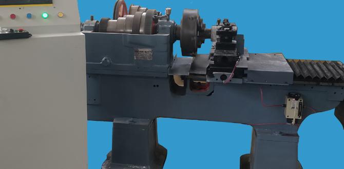
Milling Machine: A sturdy milling machine is essential. This could be a benchtop CNC, a manual knee mill, or even a robust mill-drill. The rigidity of your machine directly impacts the success of milling cast iron.
Workholding: A sturdy vise is critical. It must firmly grip your cast iron part and resist the forces of the milling operation. Consider vise jaws made from soft material like aluminum or even wood if you need to avoid marring the workpiece.
Coolant/Lubricant: This is vital for cast iron. It helps control heat, lubricates the cutting zone, and aids in chip evacuation.
Flood Coolant System: The best option for consistent cooling.
Mist Coolant: A good alternative for smaller shops, providing a fine spray of coolant.
Cutting Fluid/Oil: Apply manually or through a mist system. Look for lubricants specifically designed for cast iron or general-purpose machining.
Safety Gear: Absolutely non-negotiable.
Safety Glasses/Face Shield: Always protect your eyes.
Hearing Protection: Milling can be loud.
Work Gloves: For handling materials, though remove them when operating the machine itself.
Apron: To protect your clothes.
Measurement Tools: Calipers, a depth micrometer, and a dial indicator for setting up and verifying dimensions.
Deburring Tool: For cleaning up edges after milling.
Understanding Speeds and Feeds
This is where many beginners get intimidated, but it’s not as scary as it sounds for cast iron with the right tool. The goal is to find a sweet spot that keeps the tool cutting cleanly without overheating or chattering.
General Guidelines for 3/16″ Carbide End Mill in Cast Iron:
Spindle Speed (RPM): For a 3/16″ carbide end mill in cast iron, you’ll typically be in the 2000-4000 RPM range. Start on the lower end and listen/watch for signs of trouble.
Feed Rate (IPM – Inches Per Minute): This is how fast the tool moves into the material. A good starting point for a 3/16″ carbide end mill might be 3-8 IPM. This sounds slow, but for rigid cast iron with a small diameter tool, it’s often effective.
Depth of Cut (DOC): For cast iron, especially with an extra-long end mill, you might be able to take a decent radial depth of cut (how much of the tool’s diameter is engaged sideways), but a shallow axial depth of cut (how deep it cuts into the material vertically) is often preferred to manage heat and chip load.
Radial Chip Thinning (RCT): This is an important concept. When doing profile cuts (around the outside of a part), you’re not milling with the full diameter of the tool. Using a smaller chip load per tooth allows for a higher feed rate while keeping the actual chip thickness manageable.
Axial Depth of Cut (DOC): Start conservatively, perhaps 1/8″ to 3/16″ for a 3/16″ end mill. You can often increase this once you’re confident in your setup and parameters.
The Formulaic Approach (Simplified):
While you can find complex formulas, a good starting point with a 2-flute carbide end mill is:
Surface Speed (SFM): Aim for around 250-350 SFM for cast iron with uncoated carbide.
Chip Load per Tooth (CL): For a 3/16″ end mill, this is often in the range of 0.0015″ – 0.003″.
Then, calculate:
RPM = (SFM 12) / (Pi Tool Diameter)
For 300 SFM and a 0.1875″ diameter: (300 12) / (3.14159 0.1875) ≈ 6110 RPM. This is a bit high for many typical shop machines and often indicates that for softer cast irons, you might need to back off SFM or use a coated tool.
Feed Rate (IPM) = RPM Number of Flutes Chip Load per Tooth
Using ~3500 RPM, 2 flutes, and 0.002″ CL: 3500 2 0.002 = 14 IPM. This is likely too fast for a beginner, so we’ll use the general guideline of a slower feed rate.
Practical Advice: Always check the manufacturer’s recommendations for your specific end mill, as they often provide starting points for speeds and feeds for various materials. For example, a reputable manufacturer might suggest specific numbers for “cast iron.”
Where to Find Reliable Charts:
Machinery’s Handbook (a classic resource)
Tool manufacturer websites (e.g., Sandvik Coromant, Kennametal, Iscar) often have online calculators or downloadable guides.
Reputable machining forums and educational sites. Look for .edu or .gov sites for authoritative data. For instance, the National Center for Machining Science and Engineering (NIST) often publishes relevant data indirectly through research.
Step-by-Step: Milling Cast Iron with Your Extra-Long End Mill
Let’s get down to business. Follow these steps to mill your cast iron part successfully.
Step 1: Secure Your Workpiece
Clean the Vise Jaws and Workpiece: Remove any debris that could cause the part to shift.
Position the Workpiece: Place the cast iron part firmly in the milling vise. Ensure it’s as close to the vise’s fixed jaw as possible for maximum rigidity.
Tighten Securely: Use a wrench or vise handle to tighten the vise. You want it very secure; cast iron milling forces can easily dislodge less-than-firmly held parts. Don’t overtighten to the point of crushing or deforming the workpiece, especially if it’s already been machined or is delicate.
Step 2: Set Up the End Mill
Install the End Mill: Place the extra-long carbide end mill into your milling machine’s collet or tool holder.
Tighten the Collet: Ensure the collet is securely tightened to hold the end mill firmly and without runout (wobble).
Zero Your Axes: Using your measurement tools, carefully set your machine’s X, Y, and Z zero points. This is crucial for accurate machining. If plunging a hole, ensure your Z zero is accurately set from the top surface of your workpiece.
Step 3: Apply Coolant and Set Parameters
Turn On Coolant: Start your flood or mist coolant system. Ensure it’s directed precisely at the cutting zone.
Program/Set Speeds and Feeds: Input your chosen spindle speed and feed rate into your CNC controller, or set your manual machine’s controls accordingly. Remember to start conservatively, especially if you’re new to this. Listening to the cut and watching for chip formation is your best guide.
Step 4: The First Cut – Plunge or Climb Milling
This is where you get into the material. For cast iron, and especially with an end mill that plunges into the material, it’s often best to use a climb milling strategy.
What is Climb Milling? In climb milling (also called conventional milling), the tool rotates in the same direction as the feed movement. This means chips get thinner as the tooth exits the cut, rather than thicker (as in conventional milling). This results in less tool wear, better chip evacuation, and often a smoother finish and less chatter for materials like cast iron.
How to Achieve Climb Milling: For CNC, your CAM software will typically handle this. For manual milling, you’ll need to ensure you’re feeding the workpiece into the cutter’s rotation.
Performing the Cut:
1. Engage Slowly: Don’t just slam the feed rate to its maximum. Start feeding at a moderate pace and listen to the sound. A smooth, consistent humming sound is good. A grinding or chattering sound means you need to adjust your speeds, feeds, or depth of cut.
2. Observe Chip Formation: What color and size are the chips? Small, fluffy chips are good. Large, gummy chips can indicate you’re feeding too fast or not cooling enough. Dark, heat-blued chips indicate too much heat.
3. Monitor Tool and Workpiece: Keep an eye on the end mill for any signs of wear or damage, and check the workpiece for any unexpected movement.
Step 5: Making Multiple Passes (If Necessary)
Depth of Cut (Axial): If your initial depth of cut isn’t enough, you can increase it for subsequent passes. For cast iron, taking shallower passes allows coolant to work more effectively and prevents overwhelming chip evacuation.
Radial Depth of Cut: When profiling (milling around the edge of a part), you’ll typically engage the tool radially. For cast iron, a smaller radial depth of cut, combined with a slightly higher feed rate (Radial Chip Thinning principle), can be more effective than taking a large bite sideways with the full diameter.
Step 6: Finishing and Inspection
Final Pass: Sometimes, a finishing pass with a very light depth of cut (e.g., 0.010″) and a slightly higher feed rate can provide an exceptionally smooth surface finish.
Deburr: Once milling is complete, use a deburring tool to remove any sharp edges left by the end mill.
Measure and Verify: Use your calipers and other measuring tools to ensure your part is within the desired tolerances.
Optimizing for Reduced Chatter
Chatter is the bane of a machinist’s existence. Here’s how to specifically use your extra-long carbide end mill to combat it in cast iron:
Rigidity is King: Ensure your workpiece is clamped rock-solid. Any movement will encourage chatter.
Tool Holder Quality: Use a good quality collet or tool holder with minimal runout. A worn holder will introduce vibration.
Feed Rate Adjustment: Often, the solution to chatter is to increase the feed rate slightly. This is counter-intuitive but can help the tool “outrun” the vibration by creating thicker chips. This is where the Radial Chip Thinning principle becomes very useful in profiling.
Spindle Speed Adjustment: In some cases, slightly increasing or decreasing spindle speed can “tune out” the chatter frequency.
Depth of Cut: Experiment with shallower or deeper cuts. Sometimes a shallower cut lets the tool vibrate more, while a deeper cut can engage more cutting surface, stabilizing it.
Tool Geometry: As mentioned, a small corner radius adds strength. If your tool has sharp corners, try one with a slight radius.
Coolant Flow: Ensure coolant is efficiently clearing chips and cooling the cut. Clogged flutes or poor coolant delivery are common chatter culprits.
Common Pitfalls and How to Avoid Them
Bad Chip Evacuation
Problem: Chips build up in the flutes, recut, and cause tool wear or breakage.
Solution:** Use a 2-flute end mill, ensure sufficient coolant, feed at an appropriate rate for your DOC, and consider using a tool with enhanced chip-breaking features or a helix angle designed for cast iron.