Have you ever wondered how metal parts are made? It’s fascinating how a simple block of metal can turn into complex shapes with just a machine. In this world of metalworking, the manual metal lathe shines brightly.
But what if we could design these machines using computers? That’s where manual metal lathe CAD design comes in. CAD stands for Computer-Aided Design. This helps engineers create detailed blueprints for building lathes.
Imagine sketching out a beautiful car or an intricate toy. CAD makes it possible to visualize and plan every tiny detail. The best part? You can correct mistakes easily, saving both time and materials.
Curious about how these designs work? This article will explore the exciting world of manual metal lathe CAD design. You will learn why it matters and how it transforms metalworking.
Manual Metal Lathe Cad Design: A Comprehensive Guide

Manual Metal Lathe CAD Design
Manual metal lathe CAD design helps create precise models for machining. This design process allows users to visualize parts before they are made. Have you ever wondered how parts fit together? CAD software shows these details clearly. Users can design intricate shapes, ensuring everything matches perfectly. Fun fact: many professionals start with simple shapes to learn. This step is crucial for mastering the craft. With practice, anyone can transform ideas into reality using manual metal lathes!Understanding the Basics of Manual Metal Lathes
Definition and function of a manual metal lathe. Key components and their roles in lathe operation.A manual metal lathe is a machine that shapes metal into useful forms. It spins metal while cutting tools remove material. This tool is essential in many workshops and schools for projects. Key parts of a manual lathe include:
- Headstock: Holds the spindle, which spins the metal.
- Tailstock: Supports the other end of the metal piece.
- Carriage: Moves the cutting tool back and forth.
- Cross-slide: Controls the tool’s position.
Each part plays a vital role in making precise shapes and sizes. Working with a manual lathe helps users create many cool things!
What is a manual metal lathe used for?
A manual metal lathe is used for turning, shaping, and creating metal parts.It helps in making everything from simple tools to complex machine parts.
The Importance of CAD in Metal Lathe Design
Benefits of using CAD for manual lathe designs. Comparison of traditional design methods vs. CAD techniques.Using CAD in metal lathe design has many benefits. First, it allows precise designs without human error. Traditional methods can lead to mistakes on paper. CAD also speeds up the design process. You can easily make changes without starting over. Here are some key benefits:
- Easy Targeting: Adjust designs quickly with a click.
- Better Visuals: 3D models help see the final product.
- Time-Saving: Finish designs faster than by hand.
In simple terms, CAD is like having an amazing tool that helps make better designs quickly!
What are the key advantages of using CAD?
CAD gives metal lathe designers accuracy, speed, and visibility in their work. It helps create precise drawings, which leads to better metal parts!
Choosing the Right CAD Software for Metal Lathe Design
Popular CAD software options available. Criteria for selecting appropriate CAD tools based on project needs.When it comes to metal lathe design, picking the right CAD software is like choosing the perfect tool from a toolbox. Popular options include AutoCAD, SolidWorks, and Fusion 360. These tools are user-friendly and packed with features. To choose the best fit, consider your project’s needs. Do you want 3D modeling or simple 2D drawings? Remember, the right software makes design as easy as pie. After all, who needs stress when designing metal lathe parts?
| Software | Features | Best For |
|---|---|---|
| AutoCAD | 2D and 3D design | Architects |
| SolidWorks | 3D modeling | Engineers |
| Fusion 360 | Collaboration tools | Hobbyists |
Step-by-Step Guide to Creating CAD Designs for Manual Metal Lathes
Initial planning and design considerations. Detailed steps for modeling components in CAD software.Before you start making your CAD designs for a manual metal lathe, consider some important steps. First, think about what you want to create. It’s helpful to sketch your ideas on paper. Next, check measurements. Here are some design points to think about:
- Choose your materials.
- Plan the size of parts.
- Think about how parts will fit together.
Now, let’s look at the steps for modeling in CAD software. Open your CAD program and create a new project. Draw the basic shapes of your components. Use features to add details, like holes or curves. Don’t forget to save your work often!
What are the essential steps in CAD modeling for a lathe?
To model in CAD:
- Start with simple shapes.
- Add details gradually.
- Use tools for precision.
Common Challenges in Manual Metal Lathe CAD Design
Typical issues encountered during the design process. Tips for troubleshooting and overcoming design hurdles.Designing with a manual metal lathe can feel like trying to solve a puzzle with missing pieces. Common issues include misalignments, coding errors, and unexpected tool wear. These problems can slow down your progress and test your patience. To troubleshoot, always double-check your dimensions and settings. If something doesn’t fit, step back and rethink your approach. Remember, it’s often easier to fix a mistake than to make a perfect piece right away!
| Challenge | Tip |
|---|---|
| Misalignments | Check your setup carefully! |
| Coding Errors | Review your code line by line. |
| Tool Wear | Replace tools regularly to maintain quality. |
Best Practices for Manual Metal Lathe CAD Design
Key techniques for optimizing designs for functionality and efficiency. Importance of regular design reviews and feedback loops.Designing a manual metal lathe in CAD can feel like juggling flaming torches—exciting but tricky! To optimize your designs, focus on function and efficiency. Use simple shapes that work well together, minimizing waste and time. Regular design reviews are key; think of them as family dinners where everyone shares ideas, but with fewer potatoes! Quick feedback loops can help catch mistakes early, making your design smoother and more effective.
| Best Practices | Benefits |
|---|---|
| Use simple shapes | Reduces waste |
| Frequent reviews | Improves collaboration |
| Feedback loops | Catches mistakes early |
Case Studies: Successful Manual Metal Lathe Designs Using CAD
Examples of innovative designs from various industries. Lessons learned from realworld applications and implementations.Many industries show how effective manual metal lathe designs can be when paired with CAD technology. For example, automotive companies use lathe designs to create precise engine parts. In aerospace, designs ensure safety and performance. Here are some lessons learned:
- Collaboration between design and manufacturing speeds up creation.
- Testing designs in real-world settings improves quality.
- Creative solutions can lower costs and improve efficiency.
These innovations not only boost production but also inspire future designs. A well-designed lathe can transform industries and spark new ideas.
What are examples of successful CAD designs in manual metal lathes?
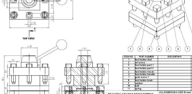
A successful CAD design in manual metal lathes includes custom tool holders and unique fixture designs for better machining accuracy.
Future Trends in Manual Metal Lathe CAD Design
Emerging technologies and their impact on CAD for metal lathes. Predictions for the future of manual metal lathe design and engineering practices.New technologies are changing manual metal lathe design. 3D printing and AI software are helping to create better designs faster. These tools can help engineers find errors early and improve accuracy. In the future, we may see:
- More automated processes in design
- Integration with virtual and augmented reality
- Greater focus on sustainability and eco-friendly materials
Predictions show that design will be quicker and easier. Designers might spend less time on small details. Instead, they will focus on big ideas. The future looks bright for manual metal lathe design!
What is the impact of new technology on manual metal lathe CAD design?
New technology makes CAD design faster and more accurate. This helps designers create better products with fewer mistakes.
Conclusion
In summary, manual metal lathe CAD design combines creativity with technical skills. You can visualize projects and ensure accuracy. Learning these skills opens opportunities in engineering and design. Explore online tutorials or courses to improve your skills. Start practicing today, and you’ll be ready to create amazing projects with your own metal lathe!FAQs
Sure! Here Are Five Related Questions On The Topic Of Manual Metal Lathe Cad Design:Sure! Here are five related questions about manual metal lathe CAD design: 1. What is a manual metal lathe? A manual metal lathe is a machine that shapes metal. It spins metal pieces and cuts them into the right shapes. 2. How does CAD help with lathe design? CAD stands for Computer-Aided Design. It helps us draw and plan designs on a computer before making them. 3. What can you make with a lathe? You can make lots of things, like metal parts, tools, and even toys. 4. Do you need special skills to use a lathe? Yes, you need to learn how to use it safely and correctly. Practice helps a lot! 5. Why is safety important when using a lathe? Safety is important because lathes can be dangerous. We must wear safety gear and follow rules to avoid accidents.
Sure! Just give me the question you’d like me to answer, and I’ll provide a simple, clear response for you.
What Are The Key Features To Consider When Designing A Cad Model For A Manual Metal Lathe?When designing a CAD model for a manual metal lathe, you should think about the size first. Make sure the parts fit well on the lathe. Next, check the shape of the pieces. They need to have smooth edges for easy cutting. You also want to think about how deep the cuts will be; this affects how the metal shapes up. Finally, make sure your design is strong enough to handle the work without breaking.
How Can Cad Software Assist In Simulating The Operational Parameters Of A Manual Metal Lathe Design?CAD software helps us design and test how a metal lathe works. We can see how the machine moves and cuts without building it first. You can change settings, like speed, to see what happens. This way, we find the best ways to make things before using real metal. It saves time and effort!
What Materials Are Commonly Used In The Construction Of Manual Metal Lathes, And How Can These Materials Be Represented In Cad?Manual metal lathes are usually made from steel and cast iron. Steel is strong and helps the lathe last a long time. Cast iron is heavy, which keeps the lathe steady while it works. In Computer-Aided Design (CAD), we can show these materials by using textures and colors to match real life. This helps us see how the lathe will look and work before building it.
How Can Designers Ensure That Their Cad Designs Accommodate Standard Tooling And Attachments For Manual Metal Lathes?To make sure your CAD designs work with manual metal lathes, you should start by knowing the sizes of standard tools. You can check the tool specifications and keep these sizes in your design. It helps to use parts that fit together easily. You can also ask other people who work with lathes for advice. Finally, test your designs with real tools to see if they fit well.
What Are The Best Practices For Creating Detailed Technical Drawings From Cad Models Of Manual Metal Lathes For Manufacturing Purposes?To make good drawings from CAD models of metal lathes, we should follow some simple steps. First, we need to add all the important details, like measurements and labels. Next, we can use clear lines and styles so everyone can understand the drawing easily. It’s also helpful to use notes to explain special parts. Finally, we should check our drawings to make sure everything is correct and clear.
{“@context”:”https://schema.org”,”@type”: “FAQPage”,”mainEntity”:[{“@type”: “Question”,”name”: “Sure! Here Are Five Related Questions On The Topic Of Manual Metal Lathe Cad Design:”,”acceptedAnswer”: {“@type”: “Answer”,”text”: “Sure! Here are five related questions about manual metal lathe CAD design: 1. What is a manual metal lathe? A manual metal lathe is a machine that shapes metal. It spins metal pieces and cuts them into the right shapes. 2. How does CAD help with lathe design? CAD stands for Computer-Aided Design. It helps us draw and plan designs on a computer before making them. 3. What can you make with a lathe? You can make lots of things, like metal parts, tools, and even toys. 4. Do you need special skills to use a lathe? Yes, you need to learn how to use it safely and correctly. Practice helps a lot! 5. Why is safety important when using a lathe? Safety is important because lathes can be dangerous. We must wear safety gear and follow rules to avoid accidents.”}},{“@type”: “Question”,”name”: “”,”acceptedAnswer”: {“@type”: “Answer”,”text”: “Sure! Just give me the question you’d like me to answer, and I’ll provide a simple, clear response for you.”}},{“@type”: “Question”,”name”: “What Are The Key Features To Consider When Designing A Cad Model For A Manual Metal Lathe?”,”acceptedAnswer”: {“@type”: “Answer”,”text”: “When designing a CAD model for a manual metal lathe, you should think about the size first. Make sure the parts fit well on the lathe. Next, check the shape of the pieces. They need to have smooth edges for easy cutting. You also want to think about how deep the cuts will be; this affects how the metal shapes up. Finally, make sure your design is strong enough to handle the work without breaking.”}},{“@type”: “Question”,”name”: “How Can Cad Software Assist In Simulating The Operational Parameters Of A Manual Metal Lathe Design?”,”acceptedAnswer”: {“@type”: “Answer”,”text”: “CAD software helps us design and test how a metal lathe works. We can see how the machine moves and cuts without building it first. You can change settings, like speed, to see what happens. This way, we find the best ways to make things before using real metal. It saves time and effort!”}},{“@type”: “Question”,”name”: “What Materials Are Commonly Used In The Construction Of Manual Metal Lathes, And How Can These Materials Be Represented In Cad?”,”acceptedAnswer”: {“@type”: “Answer”,”text”: “Manual metal lathes are usually made from steel and cast iron. Steel is strong and helps the lathe last a long time. Cast iron is heavy, which keeps the lathe steady while it works. In Computer-Aided Design (CAD), we can show these materials by using textures and colors to match real life. This helps us see how the lathe will look and work before building it.”}},{“@type”: “Question”,”name”: “How Can Designers Ensure That Their Cad Designs Accommodate Standard Tooling And Attachments For Manual Metal Lathes?”,”acceptedAnswer”: {“@type”: “Answer”,”text”: “To make sure your CAD designs work with manual metal lathes, you should start by knowing the sizes of standard tools. You can check the tool specifications and keep these sizes in your design. It helps to use parts that fit together easily. You can also ask other people who work with lathes for advice. Finally, test your designs with real tools to see if they fit well.”}},{“@type”: “Question”,”name”: “What Are The Best Practices For Creating Detailed Technical Drawings From Cad Models Of Manual Metal Lathes For Manufacturing Purposes?”,”acceptedAnswer”: {“@type”: “Answer”,”text”: “To make good drawings from CAD models of metal lathes, we should follow some simple steps. First, we need to add all the important details, like measurements and labels. Next, we can use clear lines and styles so everyone can understand the drawing easily. It’s also helpful to use notes to explain special parts. Finally, we should check our drawings to make sure everything is correct and clear.”}}]}
