Have you ever wondered how machines work? One secret lies in the milling tool assembly. This essential part plays a big role in turning raw materials into finished products.
Imagine you’re in a workshop, watching a milling machine spin and cut. It looks magical, doesn’t it? But what makes it tick? Understanding the milling tool assembly diagram can help you see the magic behind the scenes.
In this guide, we will explore how each part fits together in the milling tool assembly. You’ll discover tips and tricks to make sense of the diagram.
Did you know that milling machines can create everything from car parts to tiny toys? Learning about this can spark a new interest in you. So, let’s dive in and unravel the mystery of milling tool assemblies together!
A Comprehensive Milling Tool Assembly Diagram Guide

Milling Tool Assembly Diagram Guide
Milling tools shape materials like metal and wood. Understanding a milling tool assembly diagram is key for anyone interested in machining. The diagram shows how parts fit together and function. It also helps with troubleshooting problems. Knowing this can save time and improve your work quality. Did you know that even small errors in assembly can lead to big issues? Learning about these diagrams can make you a better machinist and boost your skills.Understanding Milling Tools
Definition and purpose of milling tools. Types of milling tools commonly used in manufacturing.Milling tools are special machines used to cut materials like wood and metal. Their main purpose is to shape and size these materials. Different types of milling tools help with various jobs. Here are some common types:
- End Mills: Great for cutting flat surfaces.
- Face Mills: Used for bigger surfaces, making them smooth.
- Ball Nose Mills: Perfect for rounded shapes.
- Taps: Help create holes with threads.
Using the right milling tool makes work easier and more accurate!
What are common materials cut by milling tools?
Milling tools commonly cut materials like aluminum, wood, plastic, and steel. Each tool is designed for different materials to ensure precise results.
Components of a Milling Tool Assembly
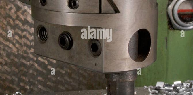
Detailed description of each component (cutter, spindle, etc.). Importance of each part in the overall functionality.Milling tools have important parts that work together. Here are some main components:
- Cutter: This spinning part removes material. It shapes and cuts the workpiece.
- Spindle: This holds the cutter in place. It allows the cutter to spin quickly.
- Table: The table supports the workpiece. It moves up and down or side to side.
- Feed Mechanism: This moves the workpiece toward the cutter. It helps control how fast the cutting happens.
Each part is vital for smooth operation. If one fails, the whole tool can stop. Together, they create precise shapes you need.
What is the function of a milling tool cutter?
The cutter shapes and cuts the material as it spins, removing unwanted parts to create desired shapes.
Why is the spindle important?
The spindle securely holds the cutter, allowing it to spin at high speeds for effective cutting.
Interpreting Milling Tool Assembly Diagrams
Explanation of common symbols and notations used in diagrams. Stepbystep guide to reading and understanding a milling tool assembly diagram.Reading a milling tool assembly diagram is easier than you think. Diagrams use symbols and notations to show how parts fit together. Common symbols include circles for holes, lines for connections, and arrows for movement. Start from the top. Follow these steps:
- Identify the main parts.
- Look at the symbols.
- Check for notes that explain details.
- Follow the arrows for assembly order.
With practice, you will understand these diagrams well!
What are common symbols in milling tool diagrams?
Common symbols include circles for holes, lines for connections, and arrows for direction.
Steps to Assemble a Milling Tool
Comprehensive list of materials and tools needed for assembly. Detailed assembly instructions with illustrations or diagrams.To build your milling tool, gather some important things first. You will need:
- Milling tool parts
- Screwdriver
- Wrench
- Measuring tape
- Safety goggles
Next, follow these steps:
- Start with the base. Attach it securely.
- Connect the motor. Make sure it fits tightly.
- Join the spindle. This part spins the tools.
- Install the guards. Keep your hands safe!
- Finally, check all screws. Ensure everything is fastened well.
Use a milling tool assembly diagram to help you see how it all fits together!
What tools do I need for milling tool assembly?
For milling tool assembly, you need a screwdriver, wrench, measuring tape, and safety goggles. These tools help ensure a strong and safe build.
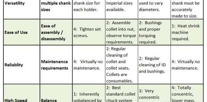
Maintenance Tips for Milling Tool Assemblies
Key practices for maintaining milling tools for longevity. Signs of wear and when to replace assembly components.To extend the life of your milling tools, regular maintenance is crucial. Clean them often to remove dust and debris that can cause damage. Check for signs of wear, like chips or cracks. If you notice a change in performance, it’s time to replace parts. Remember, a tool in good shape works better and lasts longer. Just like a car needs oil, your tools need care!
| Maintenance Task | Frequency | Signs of Wear |
|---|---|---|
| Clean Tools | After Every Use | Dirt Build-Up |
| Inspect Components | Weekly | Chips or Cracks |
| Replace Worn Parts | As Needed | Poor Performance |
Advanced Techniques in Milling Tool Assembly
Discussion on precision assembly techniques. Use of technology and software in modern milling tool assembly.Precision in milling tool assembly is crucial. It ensures everything fits perfectly. Modern technology helps a lot. Advanced software aids in designs and measurements. These tools minimize errors. Here are some key techniques used:
- 3D modeling for accurate designs
- Computer-aided design (CAD) for precision
- Laser guides for alignment
- Automated assembly systems for speed
This combination of techniques increases the quality of milling tools. It also saves time during assembly.
What tools do we use for milling assembly?
Common tools include CAD software, laser alignment tools, and automated machines.
These advances change how we work with milling tools. They ensure parts fit together just right! What do you think about using robots in assembly?
Resources for Further Learning
Recommended books, websites, and online courses. Professional organizations and communities for milling tool assembly enthusiasts.There are many great resources for learning about milling tool assembly. Here are some recommended options:
- Books: Check out “Machining Fundamentals” for an introduction.
- Websites: Visit MillingTool.com for tips and diagrams.
- Online Courses: Look for courses on platforms like Udemy or Coursera.
- Professional Organizations: Join groups like the Society of Manufacturing Engineers to connect with others.
- Communities: Engage with enthusiasts on forums like Reddit and Facebook groups.
These resources will help you learn and improve your skills!
Where can I find more information on milling tools?
You can find more information online. Check out websites dedicated to milling tools. Watch videos on YouTube for visual lessons. Joining a community can also help you ask questions and get quick answers.
Conclusion
In conclusion, a milling tool assembly diagram guide helps you understand how to assemble your tools. It shows each part clearly and makes the process easy. When you follow the guide, you save time and improve your work quality. To learn more, check additional resources or practice assembling with a friend. Happy milling!FAQs
What Are The Essential Components Included In A Milling Tool Assembly Diagram?A milling tool assembly diagram shows different parts of a machine that cuts shapes in materials. You will see the milling cutter, which does the cutting. There’s also a holder that keeps the cutter in place. The spindle is important too; it spins the cutter fast. We also see the base, which supports everything and keeps it steady.
How Can I Accurately Interpret The Specifications On A Milling Tool Assembly Diagram?To understand a milling tool assembly diagram, start by looking at the labels. Each part has a name and number. Read the notes to see what each part does. We can use a ruler to measure sizes. If you get confused, ask a grown-up for help!
What Safety Precautions Should Be Followed When Assembling A Milling Tool As Outlined In The Diagram?When assembling a milling tool, always wear safety glasses to protect your eyes. Keep your hands away from sharp parts to avoid cuts. Make sure the tool is turned off and unplugged before you start. Use the right tools for assembly to prevent accidents. Finally, follow the steps in the diagram carefully to do it right.
Can You Explain The Function Of Each Part Labeled In A Typical Milling Tool Assembly Diagram?Sure! In a milling tool assembly, the main parts are the tool holder, cutting tool, and arbor. 1. The **tool holder** holds the cutting tool tightly in place. 2. The **cutting tool** does the actual cutting to shape the material. 3. The **arbor** connects the tool holder to the machine so everything spins together. All these parts work together to help us cut materials accurately!
What Are Common Mistakes To Avoid When Assembling A Milling Tool Based On The Diagram?When putting a milling tool together, be careful not to mix up the parts. Always check the order of assembly in the diagram. Make sure everything is tight so it won’t come apart while working. Don’t forget to wear safety gear like goggles! Finally, double-check that you have all the pieces before starting.