Have you ever wondered how precise parts are made? Imagine a machine spinning metal into perfect shapes. That’s where a precision metal lathe comes in.
Using CAD design, engineers can create detailed plans for these lathes. This helps in making everything from tiny screws to large machine parts.
Did you know that modern lathes can produce items with amazing accuracy? Every little detail counts. With CAD design, you can visualize your project before making it. This saves time and money.
In this article, we will explore how precision metal lathe CAD design works. You’ll discover tips and tricks that can change the way you create. Are you ready to dive into the world of metalworking? Let’s get started!
Precision Metal Lathe Cad Design: Unlocking Metalcraft Potential

Precision Metal Lathe CAD Design
Precision metal lathe CAD design is a powerful tool for creating detailed parts. Have you ever wondered how machines make exact shapes? This design allows engineers to visualize and plan pieces before they are built. With CAD, they can adjust sizes and shapes quickly. It saves time and materials, making production smarter. When designing, users input specific measurements for accuracy. This tool is essential for anyone interested in metalworking or engineering projects!What is a Precision Metal Lathe?
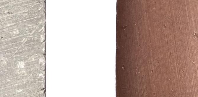
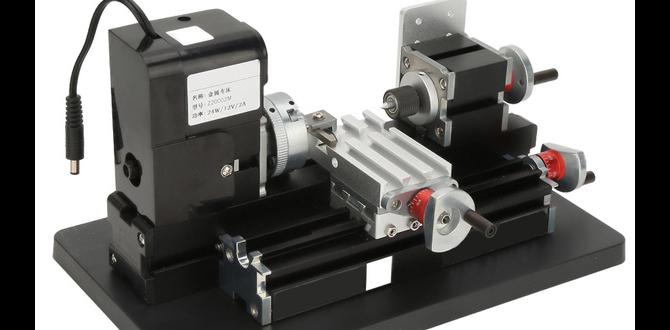
Definition and explanation of precision metal lathes. Common applications and industries using precision metal lathes.A precision metal lathe is a special machine. It shapes metal with exact measurements. This tool spins metal pieces fast to cut them into desired shapes. Lathes are used in many fields, such as:
- Automotive
- Aerospace
- Manufacturing
- Machining
They make parts like gears and shafts. Precision lathes help create items that fit perfectly, which is very important in many industries.
What are the benefits of using a precision metal lathe?
Using a precision metal lathe leads to improved accuracy and smooth finishes. This means parts work better and last longer. The cost goes down since mistakes are fewer and production is faster.
Key Features of Precision Metal Lathes
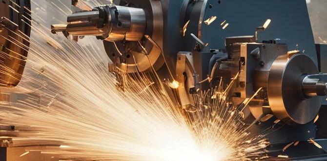
Essential components of precision metal lathes. Technologies used in modern precision metal lathes.Precision metal lathes are fascinating machines. They have many important parts that work together. Key components include:
- High-speed spindle for rotating materials
- Tool holders for securing cutting tools
- Carriages that move tools along materials
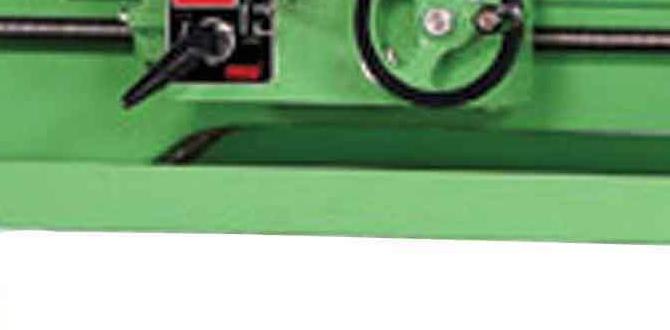
What are essential components of precision metal lathes?
Essential parts include a spindle, tool holders, and carriages. These components help shape metal accurately and efficiently.
What technologies are used in modern precision metal lathes?
Modern lathes use CNC technology. This technology allows computers to control the lathes, making them precise and fast.
CAD Software Options for Precision Metal Lathe Design
Popular CAD software tools for lathe design. Comparison of features and pricing of different CAD software.When designing a precision metal lathe, choosing the right CAD software is key. Popular options include **AutoCAD**, **Fusion 360**, and **SolidWorks**. Each has unique features and price points. For instance, AutoCAD is known for its strong 2D drafting capabilities. Fusion 360 shines in 3D modeling and is great for collaboration. SolidWorks provides powerful simulation tools but can be more expensive. Let’s look at some comparisons in the table below:
| Software | Features | Starting Price |
|---|---|---|
| AutoCAD | 2D Drafting | $1,690/year |
| Fusion 360 | 3D Modeling, Collaboration | $495/year |
| SolidWorks | Simulation Tools | $3,995 + Annual Fee |
Each software has its own charm—like picking the best chocolate in a candy store! So, weigh your options wisely!
Designing a Precision Metal Lathe: Step-by-Step Process
Initial design considerations and requirements gathering. Detailed design stages using CAD.Designing a metal lathe starts with gathering requirements. Think about how it will be used. Will it turn metal faster than a cheetah? Maybe not, but we can try! Next, move to the detailed design with CAD software. This tool lets you see your creation in 3D. It’s like building with blocks but with way more metal. Follow these stages:
| Stage | Description |
|---|---|
| 1. Requirements | Gather needs and ideas for the lathe. |
| 2. Sketching | Create rough drawings to visualize. |
| 3. CAD Design | Develop a detailed model using CAD software. |
| 4. Review | Check and refine the design before production. |
With careful planning and smart tools, your metal lathe dreams can spin into reality. Remember, it’s all about precision and a little creativity!
Best Practices for Creating CAD Designs for Metal Lathes
Tips for maximizing efficiency and precision in CAD designs. Common mistakes to avoid when designing metal lathes in CAD.To create amazing CAD designs for metal lathes, focus on efficiency and precision. Start with a clear plan for your design. Use simple shapes and measurements. Always double-check your work to avoid mistakes. It’s easy to make errors in dimensions or angles. Keep your workspace organized, too. A clean area helps in accurate designing.
- Measure twice, cut once.
- Avoid overcrowding your design with too many details.
- Use software tutorials for guidance.
These tips will help you avoid common issues and make great designs.
What are common mistakes in CAD design for metal lathes?
Common mistakes include incorrect measurements, complex designs, and lack of testing. Simple errors can lead to major problems later on.
Case Studies: Successful Precision Metal Lathe Designs
Examples of innovative designs in the industry. Lessons learned from each case study.In the world of precision metal lathe design, creativity shines! One standout example is the “Speedy Spinner,” which cuts project times in half. It uses unique software that allows for real-time adjustments, making it a favorite among machinists. Another great case is the “Eco-Lathe,” designed to save energy while still being powerful. It teaches us that being green can also be smart. Let’s take a look at some key lessons learned:
| Design | Key Innovation | Lesson |
|---|---|---|
| Speedy Spinner | Real-time adjustments | Efficiency is crucial! |
| Eco-Lathe | Energy savings | Smart design can help the planet! |
These examples show that thinking outside the box leads to fantastic results. Who knew metal lathes could be so much fun?
The Future of CAD in Precision Metal Lathe Design
Upcoming trends and technologies in CAD and metal lathe design. Predictions for the evolution of precision metal lathes with CAD integration.New trends in CAD technology are changing how we design precision metal lathes. For example, 3D modeling is becoming popular. This lets designers see their work in a more realistic way. Artificial intelligence is also helping make designs smarter and faster. CAD will make lathes more efficient and easier to use. In the future, we might see lathes that adjust themselves automatically. These changes will offer better tools for makers everywhere.
What are the upcoming trends in CAD for metal lathe design?
Key trends include better 3D modeling, AI support, and easy sharing of designs.
Benefits of these advancements:
- Faster design processes
- Improved accuracy in production
- Easier collaboration among teams
Conclusion
In conclusion, precision metal lathe CAD design is vital for creating accurate machine parts. It helps you visualize and plan your projects. By mastering CAD skills, you can improve your designing abilities. Start practicing with software tutorials or join a workshop. Explore more about CAD design to enhance your projects and bring your ideas to life!FAQs
Sure! Here Are Five Questions Related To Precision Metal Lathe Cad Design:Sure! Here are five questions we can explore about precision metal lathe CAD design: 1. What is a precision metal lathe? A precision metal lathe is a machine that shapes metal into different forms. 2. How does CAD help with designs? CAD, which stands for Computer-Aided Design, helps you create drawings on a computer for better accuracy. 3. Why is accuracy important? Accuracy is important because it makes sure parts fit together correctly and work well. 4. What materials can we use with a metal lathe? We can use metals like aluminum, steel, or brass to make parts. 5. How do we start designing with CAD? We start by sketching our idea on paper, then we create it on the computer using CAD software.
Sure! Please share the question you’d like me to answer.
What Are The Key Design Considerations When Creating A Cad Model For A Precision Metal Lathe?When making a CAD model for a precision metal lathe, you should think about a few important things. First, make sure the parts fit together well. This is called proper alignment. Next, consider the size and shape of each part. They need to work together smoothly. Lastly, think about how strong each part needs to be. This helps the lathe work safely and effectively.
How Can Cad Software Be Utilized To Simulate The Machining Process Of A Precision Metal Lathe?You can use CAD software to create a digital model of the metal part you want to make. Then, we can set up the metal lathe in the program. The software shows how the machine will cut and shape the metal. This helps us see if everything will work correctly before actually using the machine. It makes the process easier and safer!
What Materials Are Most Commonly Used In Precision Metal Lathe Construction, And How Can Cad Design Accommodate These Materials?Precision metal lathes are often made from steel, cast iron, and aluminum. These materials are strong and durable. CAD, which means Computer-Aided Design, helps us create detailed plans for these materials. With CAD, you can easily change designs to fit the strengths of each material. This makes it easier to build better machines that work well.
How Do Tolerances And Fits Impact The Cad Design Of A Precision Metal Lathe’S Components?Tolerances are the tiny allowances we give when making parts. They show how much the size of a part can change. Fits are about how parts connect and move together. In CAD (Computer-Aided Design) for a metal lathe, we need to choose the right tolerances and fits. This helps make sure the parts work well together and don’t get stuck or are too loose.
What Are The Benefits Of Integrating Cnc Programming Capabilities Into The Cad Design Of A Precision Metal Lathe?Integrating CNC programming into CAD design helps us make parts faster and more accurately. You can see how a part looks before making it. This means fewer mistakes and less waste. It also makes it easier to create complex shapes that are hard to do by hand. Overall, it helps us save time and make better products!