Quick Summary:
Unlock efficient copper roughing with a TiAlN ball nose end mill! This guide explains why this tool is essential for carving intricate shapes in copper, simplifying your workflow and improving results for beginner machinists.
Working with copper on a mill can be a bit tricky. Its softness means it can easily gum up your tools, leading to frustrating, inaccurate cuts. You might be experiencing this right now, wondering how to achieve clean, consistent material removal without damaging your workpiece or your cutting tool. The good news is, there’s a specific tool that makes this process much smoother and more effective. We’re going to dive into how the right end mill can transform your copper machining experience.
Many beginners struggle with soft metals like copper because they haven’t found that perfect cutting tool. It’s easy to feel overwhelmed by the variety of end mills available. But fear not! In this guide, we’ll break down exactly why a TiAlN ball nose end mill is your best friend for roughing out copper. We’ll cover what it is, why it works so well, and the best practices for using it. Let’s get your copper projects looking professional and clean!
Why TiAlN Ball Nose End Mills are a Machinist’s Secret Weapon for Copper
When you’re starting out with milling, especially with softer metals like copper, you quickly learn that not all tools are created equal. Copper is notorious for being “gummy.” This means it tends to stick to the cutting edge of a tool rather than shearing off cleanly. This can cause:
- Poor surface finish, leaving a rough, unwanted texture.
- Increased tool wear, dulling your end mill faster than you’d expect.
- The material to build up on the flutes, leading to chip welding.
- Inaccurate dimensions and shapes due to the excessive friction and material buildup.
- Potential for tool breakage if the chips get too stuck.
This is where a specialized tool comes in. The combination of a TiAlN coating and a ball nose geometry makes it incredibly effective for roughing operations in copper. Let’s break down what each part of that name means and why it’s so important:
Understanding the “TiAlN” Coating
TiAlN stands for Titanium Aluminum Nitride. It’s a modern, advanced coating applied to the surface of the end mill. Think of it as a super-hard, protective shield for the cutting edge. Here’s what makes it so beneficial for machining copper:
- Increased Hardness: TiAlN is extremely hard, which helps the end mill resist wear and abrasion. This means it stays sharp for longer, even when cutting softer, potentially “gummy” materials.
- High-Temperature Resistance: Machining generates heat. TiAlN coatings can withstand much higher temperatures than uncoated carbide or high-speed steel. This is crucial because it prevents the copper from melting and sticking to the cutting edge, a common problem known as chip welding.
- Reduced Friction: The smooth surface of the TiAlN coating helps reduce friction between the tool and the workpiece. Lower friction means less heat generated and easier chip evacuation, leading to cleaner cuts.
- Oxidation Resistance: TiAlN forms a thin layer of aluminum oxide at high temperatures, which acts as a diffusion barrier. This further prevents the workpiece material from reacting with and sticking to the tool.
For beginners, this coating translates directly into a more forgiving tool. It helps you achieve better results with less effort and stress, reducing the chances of making costly mistakes.
The Power of the “Ball Nose” Geometry
The “ball nose” part refers to the shape of the tip of the end mill. Instead of a flat tip (like a square end mill) or a pointed tip (like a drill bit), a ball nose end mill has a perfectly rounded tip, forming a hemisphere. This shape offers several advantages, especially for roughing operations:
- 3D Contouring: Ball nose end mills are ideal for creating curved or contoured surfaces. When roughing out a shape, this geometry allows it to smoothly remove material, laying the foundation for more intricate finishing cuts.
- Undercutting Capability: The rounded tip can get into corners and create radii that a square end mill cannot. This is incredibly useful for complex geometries.
- Even Material Removal: In roughing, the goal is to quickly remove bulk material. A ball nose end mill, with its consistent radius, can do this efficiently and predictably across contoured areas.
- Reduced Stress Concentration: Compared to a sharp corner, the rounded tip distributes cutting forces more evenly, which can reduce the stress on the tool and the workpiece.
Why This Combination Works Specifically for Copper (and Especially at 35 Degrees)
So, why is the TiAlN ball nose end mill 35 degree for copper for roughing so highly recommended? The “35-degree” often refers to a specific helix angle or flute design. While the exact helix angle can vary, a moderate angle like 35 degrees generally offers a good balance:
- Improved Chip Evacuation: A moderate helix angle helps to curl and lift chips away from the cutting zone efficiently. This is paramount in copper to prevent buildup and welding.
- Smooth Cutting Action: It contributes to a smoother, more continuous cut compared to tools with very steep or very shallow helix angles. This reduces vibration, which is key for precision.
- Strength: A 35-degree angle generally maintains good flute strength, which is important when you’re applying force to remove material.
When you combine the wear resistance and heat management of TiAlN, the versatile shaping capability of the ball nose, and the efficient chip handling of a 35-degree helix, you get a tool that’s perfectly suited for tackling copper. It’s designed to cut cleanly, resist the gummy nature of the metal, and last longer.
Essential Setup: Preparing for Copper Roughing
Before you even think about plunging that shiny end mill into your copper workpiece, a little preparation goes a long way. Getting your setup right ensures safety, extends tool life, and leads to much cleaner results right from the start.
Choosing the Right Ball Nose End Mill
For beginner copper roughing, you’ll likely want to start with a few key end mill types:
- Material: Carbide is generally preferred for its rigidity and ability to hold a sharp edge, especially when coated.
- Coating: As we’ve discussed, TiAlN is an excellent choice for copper.
- Geometry: Ball nose is essential for roughing complex shapes or creating radiused features.
- Diameter: A common starting point for general roughing might be 1/8″ (3mm) to 1/2″ (12mm), depending on your milling machine’s capacity and the size of your workpiece. For intricate work, smaller diameters are used.
- Number of Flutes: For softer, “gummy” materials like copper, you often want fewer flutes. A 2-flute or 3-flute end mill is typically better than a 4-flute. Fewer flutes mean larger chip gullets (the space between the flutes), which helps clear away those troublesome chips more effectively.
Workpiece Clamping: Rock Solid is Key
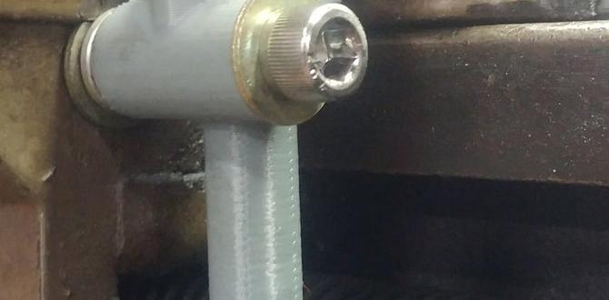
Copper can be soft, but it can also deform if not held properly. You want your workpiece to be absolutely stationary. Any movement during milling leads to inaccuracy and can be dangerous.
- Use appropriate vises or clamps: Ensure your vise jaws are clean and provide a firm grip. If using clamps, make sure they are securely fastened to the machine bed or a fixture plate.
- Protect the work surface: If you’re using clamps that might mar the visible surface of your copper, place a thin, soft material like brass shim stock or a piece of thick cardboard between the clamp and the copper.
- Avoid over-clamping: While it needs to be secure, don’t crank down so hard that you deform the copper itself, especially if it’s a thin sheet or intricate part.
Machine Setup: Speed and Feed are Crucial
This is where many beginners struggle. Too fast, and you’ll burn up your tool or break it. Too slow, and you risk rubbing and gouging, which is bad for both the copper and the tool.
Spindle Speed (RPM)
Spindle speed is measured in revolutions per minute (RPM). For copper, you generally want to run at a moderate to high spindle speed, but this depends heavily on the end mill diameter and material. A good ballpark starting point for carbide tools in copper might be:
- Small End Mills (under 1/4″ or 6mm): 3000 – 7000 RPM
- Medium End Mills (1/4″ to 1/2″ or 6mm to 12mm): 1500 – 4000 RPM
Manufacturers of end mills often provide recommended speed and feed charts for different materials. Always consult these if available. Here’s a general guide:
| End Mill Diameter | Recommended RPM Range (Copper) |
|---|---|
| 1/8″ (3mm) | 4000 – 7000 |
| 1/4″ (6mm) | 2500 – 5000 |
| 1/2″ (12mm) | 1500 – 3000 |
These are starting points. Always refer to the tool manufacturer’s recommendations and adjust based on your experience and machine rigidity.**
Feed Rate (IPM or mm/min)
The feed rate is how fast the cutting tool moves through the material. This is often expressed in inches per minute (IPM) or millimeters per minute (mm/min). For copper, you want a feed rate that allows the tool to cut rather than rub. A common mistake is feeding too slowly, which causes material to drag and build up. A typical feed rate might be expressed as:
Feed Rate (IPM) = (Chipload) x (Number of Flutes) x (RPM)
A good starting point for chipload (the amount of material removed by each tooth) in copper with a TiAlN ball nose end mill might be:
- Small End Mills (under 1/4″ or 6mm): 0.001″ – 0.003″ (0.025 – 0.075 mm) per flute
- Medium End Mills (1/4″ to 1/2″ or 6mm to 12mm): 0.003″ – 0.006″ (0.075 – 0.15 mm) per flute
A common mistake for beginners is setting the feed rate too low. For copper, you want to hear a consistent, sharp cutting sound, not a scraping or rubbing sound. If the tool sounds like it’s rubbing, increase the feed rate slightly.
Coolant or Lubricant
While copper isn’t as prone to overheating in the same way steel or aluminum is, a lubricant is still highly beneficial. It helps:
- Reduce friction and heat.
- Improve chip evacuation by preventing welding.
- Extend tool life.
- Achieve a better surface finish.
For copper, a light-duty cutting fluid, a spray lubricant, or even a bit of WD-40 can be effective. If you have flood coolant capabilities, a general-purpose or aluminum-specific coolant will work well with TiAlN coatings.
Step-by-Step: Roughing Copper with Your TiAlN Ball Nose End Mill
Now that your setup is ready, let’s get to the actual machining. We’ll focus on a common roughing task: removing bulk material to establish a basic form or cavity.
Step 1: Secure Your Workpiece
Double-check that your copper is clamped down firmly and securely. Ensure there are no loose parts, and that the workpiece won’t shift during operation. Use your soft jaws or shims if needed to protect the surface.
Step 2: Install the End Mill
Mount the correct size TiAlN ball nose end mill into your milling machine’s collet or tool holder. Ensure it’s tightened properly. A loose end mill is a recipe for disaster!
Step 3: Set Your Zero and Depth
Using your machine’s DRO (Digital Readout) or CNC controller, accurately set your X, Y, and Z zero points. For Z zero, this is typically set on the top surface of your workpiece. If you’re plunging into the material, ensure your initial Z height is above the workpiece before starting the program.
Step 4: Program Your Roughing Pass (or Manual Move)
This is where the magic happens. You’ll be telling the machine (or manually guiding it) to remove material. For roughing, you typically won’t use the full ball nose radius for slotting entire areas unless that’s the desired shape.
- Perpendicular Plunge: If plunging directly into the material, set your plunge rate significantly slower than your XY feed rate (e.g., 20-50% of the XY feed rate). This prevents shock loading the end mill as it enters the material.
- Stepover: This is how far the tool moves sideways (in X or Y) on each pass. For roughing curves and contours, a stepover might be 30-70% of the end mill diameter. For more aggressive roughing, you might use a larger stepover. For smoother initial passes, a smaller stepover is better.
- Stepdown: This is how deep the tool cuts into the material on each Z pass. For roughing, you can take larger stepdowns, but avoid taking too much at once, as this can overload the tool. A common roughing stepdown might be 0.05″ to 0.20″ (1mm to 5mm), depending on the end mill diameter and machine rigidity.
- Machining Strategy for Roughing:
- Pocketing/Cavity Roughing: If you’re creating a pocket or cavity, you’ll typically use a toolpath that moves in an offset pattern, spiraling inwards or milling back and forth across the area. The ball nose is excellent for creating radiused internal corners.
- Contour Roughing: If you’re shaping a 3D surface, you’ll define the desired shape, and the software (or your manual movements) will generate paths to remove material efficiently.
Example Roughing Pass: Imagine you need to mill out a shallow dish. You could use a ball nose end mill to mill in concentric circles, or in a raster pattern (back and forth). The ball nose will leave a slightly scalloped surface, which is fine for a roughing pass. You’d set a stepdown for how deep each ring or pass cuts.
For a more in-depth look at CAM programming for 3D surfaces, sites like the Autodesk CAM software documentation offer valuable resources on toolpath generation.
Step 5: Run the Program (or Make Manual Cuts)
Start the milling process. Listen to the machine. You should hear a consistent, sharp cutting sound. If you hear chattering, scraping, or the tool struggling, pause the operation and check your speeds, feeds, or stepover/stepdown values. Apply lubricant as needed.
Safety First: Always stand back from the machine while it’s running, wear safety glasses, and be aware of your surroundings. Never reach into the machine while it’s in motion.
Step 6: Inspect and Adjust
After a roughing pass, if you’re using multiple passes, stop the machine and inspect the workpiece. Check for:
- Material removal effectiveness.
- Surface finish quality (is it clean, or is there chip buildup?).
- Tool condition (any signs of excessive wear or chipping?).
- Dimensional accuracy.
Based on your inspection, you might need to adjust your feed rate, spindle speed, stepover, or stepdown for subsequent passes or for the next part.
Step 7: Finishing Passes (Optional but Recommended)
Once you’ve removed the bulk of the material with your roughing passes, you’ll usually want to perform one or more finishing passes. These use much lighter stepovers and stepdowns, and often a slightly different (or optimized) feed rate, to achieve a smooth, accurate final surface. You might even switch to a different type of end mill for finishing, depending on the desired surface quality.
Troubleshooting Common Issues
Even with the right tools, you might run into a few snags. Here are common problems and