Quick Summary:
For smooth, efficient aluminum ramping with a TiAlN ball nose end mill, focus on high speeds, light chip loads, and appropriate coolants. This reliable method, especially for aluminum alloys like 7075, minimizes chatter and maximizes tool life, making your cuts cleaner and faster.
Mastering Aluminum Ramping with Your TiAlN Ball Nose End Mill: A Beginner’s Guide
Ever faced that frustrating chatter or seen your ball nose end mill struggle when plunging into aluminum? It’s a common hurdle for many beginner machinists. Cutting aluminum can be tricky because it’s a “gummy” material. This means it likes to stick to your cutting tools, causing rough finishes and even tool breakage. But don’t worry! Using the right techniques and settings with your TiAlN (Titanium Aluminum Nitride) coated ball nose end mill can make all the difference. We’re going to break down the proven ramping methods that will help you achieve smooth, clean cuts, especially in tough alloys like 7075 aluminum and when using a 35-degree ramp angle.
This guide is designed to be your friendly workshop mentor, walking you through everything you need to know. We’ll cover the essential settings, coolants, and tool considerations to ensure your success. Get ready to conquer aluminum cuts with confidence!
Why Ramping? The Smart Way to Plunge
Traditional plunging, where a tool goes straight down into the material, can be tough on end mills. It creates a lot of axial pressure and can lead to tool chatter, poor surface finish, and shorter tool life. Ramping is a much smarter approach.
Imagine your milling machine taking a gentle, sloping path downwards, rather than a direct dive. That’s essentially what ramping is. The end mill engages the material with a sideways cutting motion, rather than a direct hammering one. This significantly reduces the forces acting on the tool and spindle.
For aluminum, especially with a ball nose end mill, ramping is particularly beneficial. It allows the flutes to clear chips more effectively and prevents the gummy material from building up on the cutting edges. This leads to:
- Smoother cuts
- Reduced tool wear
- Quieter operation (less chatter!)
- Better surface finish
- Ability to achieve deeper cuts without stress
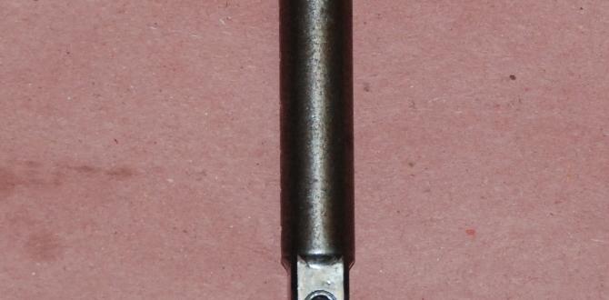
Understanding Your TiAlN Ball Nose End Mill
Your TiAlN ball nose end mill is a specialized tool. The “ball nose” shape means its tip is perfectly rounded, making it ideal for creating contoured surfaces, fillets, and 3D shapes. The TiAlN coating is crucial for aluminum machining. Here’s why:
- Hardness: TiAlN is a very hard coating, which helps resist wear and abrasion from the aluminum.
- Heat Resistance: When cutting, friction generates heat. TiAlN can withstand higher temperatures than uncoated tools, preventing the aluminum from welding itself to the end mill’s cutting edges (this is what we mean by “gummy”).
- Reduced Friction: The coating also helps reduce friction, allowing for faster cutting speeds and better chip flow.
For machining aluminum, especially alloys like 7075, it’s common to use end mills designed for non-ferrous metals. These often have polished flutes and specific geometries to help with chip evacuation. Your TiAlN coating enhances these properties.
Choosing the Right Ball Nose End Mill for Aluminum
When selecting a TiAlN ball nose end mill for aluminum, consider these factors:
- Number of Flutes: For aluminum, 2-flute or sometimes 3-flute end mills are often preferred. Fewer flutes offer better chip clearance, which is vital for sticky materials like aluminum. More flutes can provide a smoother finish but may clog if not managed correctly with coolant and feed rates.
- Coating: As we discussed, TiAlN is excellent. Other coatings like ZrN (Zirconium Nitride) are also good for aluminum, but TiAlN offers a good balance of hardness and heat resistance.
- Material: High-quality solid carbide is the standard for good performance and durability.
- Helix Angle: A standard helix angle (like 30-45 degrees) is generally good, but some specialized aluminum end mills have lower helix angles or even straight flutes with polished surfaces for maximum chip evacuation.
Key Parameters for Successful Aluminum Ramping
Getting your CNC machine’s settings right is key. Here’s a breakdown of the most important factors:
1. Spindle Speed (RPM)
Aluminum generally likes to be cut at high speeds. This helps shear the material cleanly rather than dragging it. For a typical 1/4″ or 1/2″ carbide end mill, speeds can range from 10,000 RPM up to 30,000 RPM or even higher, depending on your machine and the specific end mill.
A good starting point for many aluminum applications with TiAlN coated ball nose end mills is:
- For 1/4″ diameter: 15,000 – 25,000 RPM
- For 1/2″ diameter: 10,000 – 20,000 RPM
Always consult the tool manufacturer’s recommendations if available. Higher speeds mean the tool is engaging the material with less dwell time, which helps prevent heat buildup and chip welding.
2. Feed Rate (IPM – Inches Per Minute)
The feed rate determines how fast the end mill moves through the material. This works in conjunction with the spindle speed to control the chip load.
Chip Load: This is the thickness of the chip being removed by each cutting edge of the end mill. A proper chip load is crucial for efficient cutting. Too small, and you rub instead of cut (generating heat). Too large, and you overload the tool. Chip load is calculated as:
Chip Load = Feed Rate / (RPM × Number of Flutes)
For aluminum, you generally want a moderate chip load. Too light a chip load can lead to rubbing and poor finish. Aim for chip loads that create visible, stringy chips, not dusty or smeared material.
Here are some general starting points for Imperial units (inches) with 2-flute TiAlN ball nose end mills:
- For 1/4″ diameter: 0.001″ – 0.002″ chip load. This means a feed rate of approximately (0.0015″ × 15,000 RPM × 2 flutes) = 45 IPM.
- For 1/2″ diameter: 0.002″ – 0.004″ chip load. This means a feed rate of approximately (0.003″ × 10,000 RPM × 2 flutes) = 60 IPM.
These are starting points. You’ll often need to adjust based on how the cut feels and sounds.
3. Ramping Angle
The angle at which the end mill plunges is critical. For aluminum, a 3-degree to 7-degree ramp angle is a common and effective range.
Using a 35-degree ramp angle, while discussed in some contexts, is very aggressive and might be more suited for specialized roughing operations or specific tool geometries. For general-purpose ramping with a standard ball nose end mill, especially for beginners targeting a good finish, shallower angles like 3-5 degrees are often more forgiving.
Why a shallower angle (e.g., 3-5 degrees) is often better for beginners:
- It engages less of the cutting edge at once.
- It reduces the radial force, making chatter less likely.
- It’s more forgiving of slight inaccuracies in programming or machine rigidity.
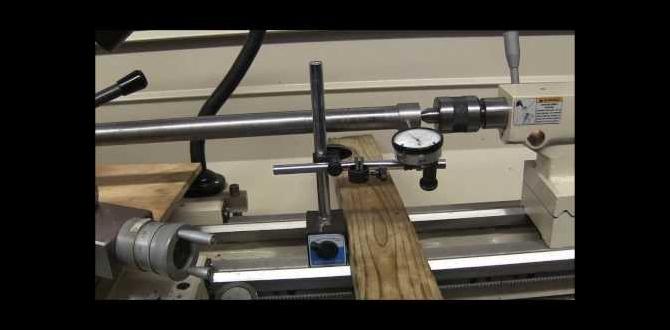
When programming, you’ll typically define the plunge path as a helix. The machine then executes this helical move downwards.
4. Cutting Depth (Stepdown)
When ramping, especially for larger depths, you might need to ramp in multiple steps. This is called stepdown.
Axial Depth of Cut (for ramping): This refers to how much vertical distance the tool covers in one ramping pass. For ball nose end mills, it’s generally recommended to keep the axial depth of cut relatively small, particularly when ramping at a shallow angle. A common guideline is to use a stepdown of 0.1 to 0.5 times the tool diameter. For 7075 aluminum, starting conservatively is wise.
Example: For a 1/2″ ball nose end mill, a stepdown of 0.1″ to 0.25″ per ramp might be a good starting point.
This ensures that the tool is not being asked to remove too much material in its axial path.
5. Radial Width of Cut (Stepover)
When milling contours or pockets, the stepover defines how much the tool moves sideways between successive paths. For ramping, if you are spiraling down in a pocket, the stepover is the distance between the helical paths. A smaller stepover results in a smoother surface but takes longer.
For contouring or 3D surfacing, a stepover of 10-40% of the tool diameter is common. For ramping to create a pocket floor, you’d typically spiral down with a stepover that creates a full engagement of the tool’s diameter to ensure the entire area is milled.
A stepover of 50% of the tool diameter is a common strategy for clearing a pocket when spiraling down.
Coolant and Lubrication: Essential for Aluminum
Aluminum is notorious for its tendency to stick to cutting tools. Proper coolant and lubrication are not optional; they are critical for success.
Types of Coolant/Lubrication for Aluminum
A flood coolant system is ideal. If you don’t have one, consider these alternatives:
- Mist Coolant: A fine mist of cutting fluid sprayed directly at the tool. This is very effective for aluminum.
- Soluble Oil Coolant: Mixed with water (concentration varies, often 5-10%), these provide good cooling and lubrication.
- Cutting Fluid/Paste: For manual milling or lighter-duty CNC, specific cutting fluids or pastes can be applied.
- Compressed Air: Can help clear chips, but offers little cooling or lubrication.
Why Coolant is Crucial for Aluminum
- Chip Evacuation: Coolant helps wash away chips, preventing them from building up on the tool and clogging the flutes.
- Heat Dissipation: It cools the cutting zone, preventing the aluminum from softening or welding to the tool.
- Lubrication: Reduces friction between the tool and workpiece, leading to a better finish and longer tool life.
For machining aluminum with a TiAlN ball nose end mill, a high-quality soluble oil or a dedicated aluminum cutting fluid is highly recommended. Ensure the concentration is correct as specified by the coolant manufacturer. You can find excellent resources on metalworking fluids from organizations like the Machinery Lubricants website.
Proven Ramping Strategies for 7075 Aluminum
7075 aluminum is a strong, heat-treatable alloy often used in aerospace and demanding applications. It can be more challenging to machine than softer aluminum alloys. Here’s how your TiAlN ball nose end mill can handle it:
Strategy 1: Helical Plunging into a Pocket
This is a very common and effective method for creating a circular opening or clearing a pocket. Instead of plunging straight down, the end mill moves in a helical (spiral) path.
- Program the Path: In your CAM software, define a helical interpolation toolpath. Specify the diameter of the helix (usually the tool diameter or slightly larger if you’re clearing an opening), the ramp angle (e.g., 3-5 degrees), and the total depth.
- Set Speeds and Feeds: Use the parameters discussed earlier, leaning towards the faster end for RPM, with an appropriate chip load for 7075.
- Ensure Coolant: A strong flow of coolant is essential for 7075.
- Start and Finish: The tool enters the material and spirals down to the programmed depth. It then exits the material, usually with a lead-out move.
This method reduces the cutting forces on the tool significantly compared to a straight plunge.
Strategy 2: Linear Ramping
This involves the tool ramping down at an angle along a straight line. This is useful for creating angled surfaces or features.
- Program the Path: Program a linear move that gradually descends into the material. The CAM software will typically handle the angled path.
- Ramp Angle: A 3-5 degree angle is a good start. For steeper ramps, you might need to reduce feed rates considerably to manage the forces.
- Multiple Passes: If the desired ramp depth is significant, you may need to perform the linear ramp in multiple passes, each at a shallower depth, to avoid overloading the tool.
- Tool Engagement: Ensure the end mill is effectively engaged at the bottom of the ramp on each pass.
Strategy 3: Tapered Ramping
This combines linear ramping with a slight change in diameter of the ramp. It’s essentially a sloped hole or counterbore.
- Program the Path: Define a path that moves linearly downwards while simultaneously moving radially outwards or inwards.
- Control Forces: Be mindful that increasing radial engagement while ramping linearly can increase cutting forces.
- Coolant is King: Again, ample coolant is vital for such operations.
For 7075 aluminum, it’s often best to start with shallower ramping angles (3-4 degrees) and conservative depths of cut. As you gain confidence and observe the cutting action, you can gradually increase these parameters.
Machining Parameters Comparison Table
This table summarizes recommended starting points. Always remember to test and adjust based on your specific setup.
| Parameter | Typical Range (Aluminum) | Notes for 7075 / TiAlN Ball Nose |
|---|---|---|
| End Mill Diameter | 0.125″ to 1.000″ | Smaller diameters (e.g., 0.125″, 0.250″) are more prone to deflection. |
| Spindle Speed (RPM) | 10,000 – 30,000+ | Higher speeds are generally better for aluminum. Aim for the upper end of the range for smaller tools. |
| Chip Load (per flute, per revolution) | 0.0005″ – 0.004″ | For 1/4″ dia: 0.001″ – 0.002″. For 1/2″ dia: 0.002″ – 0.004″. Adjust for rigidity. |
| Feed Rate (IPM) | Calculated from RPM and Chip Load. | Start conservatively and increase if the cut is smooth. Feeds and Speeds Calculators can be helpful. |
| Ramping Angle | 3° – 7° (standard) | 3° – 5° is usually safer for beginners. Avoid very steep angles unless experienced. |
| Axial Depth of Cut (for each ramp pass) | 0.05″ – 0.25″ (approx. 10-50% of tool diameter) | Keep it conservative for 7075 to prevent tool overload. |
| Radial Stepover (for pocket clearing spiral) | 30% – 75% of tool diameter | 50% is a good general compromise. |
| Coolant | Flood, Mist, or Soluble Oil | Essential for aluminum. Flood or Mist is highly recommended for 7075. |
| Tool Coating | TiAlN, ZrN, Uncoated (polished) | TiAlN provides excellent performance. |
| Number of Flutes | 2 or 3 | 2 flutes are often preferred
Related Posts |