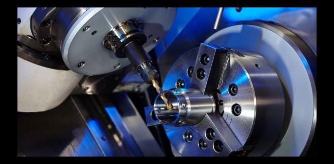
To effectively contour PEEK materials with a TIALN ball nose end mill, understanding the tool’s geometry, proper speeds and feeds, and precise setup is crucial for achieving smooth, defect-free finishes. This guide simplifies the process for beginners.
Machining PEEK can feel like a puzzle, especially when aiming for those smooth, sculpted curves. It’s easy to end up with chatter, melting, or rough edges that just won’t polish up. But don’t worry, getting a beautiful finish on PEEK with the right tool is totally achievable! The secret often lies in using the correct type of end mill and knowing how to handle it.
In this guide, we’ll walk through exactly how to use a TIALN ball nose end mill, specifically for contouring PEEK. We’ll break it down into simple, manageable steps. You’ll learn about the tool itself, the settings you need, and how to make sure your project goes smoothly from start to finish. Let’s get your machining projects looking their best!
What is a TIALN Ball Nose End Mill and Why Use It for PEEK?
A ball nose end mill is like a round-tipped cutting tool. For machining, its primary function is to create curved shapes, pockets, and features with a radius at the tip. The ‘TIALN’ coating is a special layer applied to the end mill’s surface. It’s a Titanium Aluminum Nitride coating, known for its extreme hardness, heat resistance, and ability to reduce friction.
PEEK (Polyetheretherketone) is a high-performance thermoplastic. It’s known for its excellent strength, stiffness, chemical resistance, and ability to withstand high temperatures. These properties make it ideal for demanding applications in aerospace, medical devices, and automotive industries. However, PEEK can also be prone to melting and gummy behavior when machined if the wrong parameters or tools are used. This is where the TIALN ball nose end mill shines.
Why TIALN is Great for PEEK:
- Hardness: PEEK is tough, and TIALN coating is tougher, allowing for efficient cutting with less tool wear.
- Heat Resistance: PEEK can generate heat when cut. TIALN’s high-temperature performance prevents the coating from degrading, maintaining its sharpness and effectiveness.
- Reduced Friction: The smooth TIALN surface helps chips slide away easily, preventing material from sticking to the tool and causing melting or poor surface finish.
- Ball Nose Geometry: This shape is perfect for creating smooth, continuous curves and contours, which is often a requirement when machining PEEK for its advanced applications.
Understanding the “40 Degree” Aspect
When you see “TIALN ball nose end mill 40 degree,” it’s referring to a specific characteristic of the tool. This “40 degree” typically relates to the helix angle of the flutes. The helix angle is the angle at which the cutting edges spiral around the tool’s body. For ball nose end mills, especially those used in plastics like PEEK, a 40-degree helix angle offers a good balance.
Benefits of a 40-Degree Helix Angle for PEEK:
- Chip Evacuation: Helix angles help lift chips out of the cut. A moderate angle like 40 degrees provides good chip evacuation without being so steep that it reduces the tool’s rigidity. This is crucial for PEEK, which can produce stringy chips.
- Surface Finish: The helix angle influences the cutting action and how the tool engages the material. A 40-degree angle often leads to a smoother finish on plastics compared to very steep or very shallow angles.
- Reduced Vibration: The angle can help dampen vibrations, contributing to a quieter cut and a better surface finish.
While other helix angles exist, the 40-degree is a common and versatile choice for many general-purpose machining tasks, including contouring PEEK. For specialized PEEK applications, you might find end mills designed specifically for plastics with even more optimized flute geometries.
Essential Tools and Preparations
Before you even think about cutting, having the right setup is key. It’s not just about the end mill; it’s about ensuring everything is stable and precise.
What You’ll Need:
- TIALN Ball Nose End Mill: The correct diameter for your desired contour, with the TIALN coating and a suitable helix angle (e.g., 40 degrees).
- CNC Mill or Lathe with Milling Attachment: A stable machine is crucial. Ensure it’s properly calibrated.
- Collet Chuck or Exact Collet: To hold the end mill securely. Runout (wobble) must be minimal for a good finish.
- Workholding Fixture: A robust way to hold your PEEK workpiece firmly. Clamps, vises, or custom fixtures are common.
- Coolant/Lubricant (Optional but Recommended): For PEEK, a light mist or air blast can help manage heat and clear chips. Avoid heavy flooding unless your machine and material handling system are designed for it.
- Measuring Tools: Calipers, a depth micrometer, and an edge finder/tool setter to accurately determine work offsets.
- Safety Gear: Safety glasses are a must. Consider hearing protection and appropriate gloves when handling materials.
Preparation Steps:
- Inspect Your End Mill: Check for any damage, chipping, or signs of wear on the TIALN coating. A sharp, intact tool is vital.
- Secure Your Workpiece: Mount your PEEK material firmly. It should not move at all during the machining process. For PEEK, it’s often recommended to use fixtures that grip the material without deforming it, as it can be somewhat flexible.
- Set Up the End Mill: Install the end mill into a clean collet and tighten it securely in the machine’s spindle. Ensure the collet is the correct size for the end mill shank.
- Zero Your Axes: Use an edge finder or touch probe to accurately locate the workpiece and set your X, Y, and Z-axis zero points. This is critical for ensuring your program cuts where you expect it to.
- Determine Z-Height: Measure the exact length of your tool from the spindle face (or a known reference point) to the tip of the ball nose. This information is needed for your CNC program.
Understanding Speeds and Feeds for PEEK
This is where many beginners struggle. PEEK needs specific cutting speeds (how fast the tool rotates) and feed rates (how fast the tool moves through the material) to avoid issues like melting, chip welding, and poor surface finish. Because PEEK is a plastic, its machining parameters can differ significantly from metals.
It’s always best to consult the PEEK manufacturer’s machining guidelines if available, or start with conservative speeds and feeds and gradually increase them while observing the cut. A good starting point for TIALN coated ball nose end mills on PEEK might look something like this:
Recommended Starting Speeds and Feeds (General Guideline):
| Parameter | Typical Range for PEEK | Notes |
|---|---|---|
| Surface Speed (SFM) | 150 – 300 SFM / 45 – 90 m/min | This is a common range. Higher end requires excellent chip evacuation and cooling. |
| Spindle Speed (RPM) | Calculated: (SFM 3.82) / Diameter (inches) or (m/min 1000) / (π Diameter (mm)) |
Depends on your end mill diameter. For a 1/4″ (6.35mm) end mill at 200 SFM, it’s roughly 3055 RPM. |
| Chip Load per Tooth (Inch/Rev or mm/tooth) | 0.002 – 0.006 inches/tooth 0.05 – 0.15 mm/tooth |
Crucial for preventing melting. Smaller chip loads often require higher RPMs and faster feeds to maintain. |
| Feed Rate (IPM or mm/min) | Feed Rate = Spindle Speed (RPM) Chip Load per Tooth Number of Flutes | For a 2-flute end mill at 3000 RPM with a 0.004″ chip load: IPM = 3000 0.004 * 2 = 24 IPM (approx. 600 mm/min) |
| Depth of Cut (DOC) Axial | 0.010 – 0.050 inches 0.25 – 1.25 mm |
Start shallower, especially in roughing. Can be deeper for finishing passes. |
| Width of Cut (WOC) Radial (for contouring) | 10% – 50% of tool diameter | Smaller WOC is generally better for finish. For full-form contouring, it’s usually less than 50%. |
Important Considerations for PEEK Speeds and Feeds:
- Tool Diameter: Larger diameter tools typically require slower spindle speeds and higher feed rates per tooth to maintain the same cutting force.
- Machine Rigidity: A very rigid machine can handle more aggressive parameters than a less rigid one.
- Cooling and Chip Evacuation: If you have excellent compressed air or mist cooling and a way to ensure chips are cleared, you can often push parameters slightly higher.
- Finish Requirements: For a mirror finish, you’ll use much lighter cuts and potentially slower feed rates on your final passes.
Always start conservatively. Listen to the machine and watch the chips. If the chips are melting and welding to the tool, you need to increase your feed rate or decrease your spindle speed. If you hear excessive chatter, you might need to adjust your depth of cut, width of cut, or even your feed rate. For more information on CNC machining best practices, resources like NIST (National Institute of Standards and Technology) provide foundational insights into precision manufacturing standards.
Step-by-Step: Contouring PEEK with a TIALN Ball Nose End Mill
Now, let’s get to the actual machining process. We’ll focus on creating a smooth contour, like a fillet or a rounded edge.
Step 1: Design and CAM Programming
First, you need your design. Whether it’s a 3D model or a 2D profile requiring a radius, ensure it’s accurately represented.
- Choose the Right Strategy: For contouring, you’ll typically use a “3D Contour,” “Swarf Machining,” or “Profile” toolpath strategy in your CAM software. The goal is to have the ball nose end mill follow the desired curve.
- Tool Definition: Accurately define your TIALN ball nose end mill in your CAM software (diameter, number of flutes, tip radius, coating type). This helps the software calculate appropriate cutting paths and understand its limitations.
- Set Parameters: Input your calculated speeds and feeds. Crucially, set your stepover (radial width of cut) and stepdown (axial depth of cut).
- Stepover: For a smooth surface finish, start with a stepover between 10% and 30% of the tool diameter. For excellent finishes, you might go as low as 2-5%.
- Stepdown: For roughing, you can use a larger stepdown. For finishing, use a very shallow stepdown (e.g., 0.005″ – 0.010″ or 0.125 – 0.25 mm) for the final pass to achieve the best surface quality.
Step 2: Toolpath Verification
Before sending the program to the machine, simulate your toolpath in the CAM software.
- Collision Detection: Ensure there are no collisions between the tool, holder, workpiece, or fixture.
- Visualize the Finish: Most CAM software allows you to visualize the surface finish that will be produced. This is your chance to spot potential issues with stepover or toolpath patterns.
- Analyze Cutting Motion: Check that the tool is engaging the material correctly for climb milling and that the ball nose is smoothly following the intended contour.
Step 3: Machine Setup and Initial Cuts
Load the program into your CNC machine. Double-check all your work offsets and tool lengths.
- Dry Run: Perform a “dry run” where the machine moves through the programmed path without the spindle rotating or the tool engaging the material. This is a critical safety step to verify machine movements and Z-axis clearance.
- First Cut – Air Break: For the very first cut on a new setup, you can program a small “air break” – a shallow cut just above the surface. This helps confirm your X/Y zero and tool length are correct before plunging into the material.
- Gentle Plunge: When plunging the tool into the material for the first time, ensure your feed rates are conservative.
Step 4: Executing the Contour Cut
Start the machining operation. Carefully observe the cut.
- Chip Formation: Watch the chips. They should be small, well-formed, and clear away from the cutting zone. Avoid long, stringy chips that indicate heat buildup or smearing.
- Sound: Listen for any unusual noises like chattering or squealing, which can indicate incorrect speeds, feeds, or tool pressure.
- Heat: If using a mist coolant or air blast, ensure it’s effectively cooling the cutting zone and clearing chips. Melted PEEK can stick to the tool, ruining the finish and potentially damaging the tool itself.
- Progressive Passes: If you’re making a deep contour, use multiple shallow finishing passes rather than one deep cut.
Step 5: Finishing Passes
Once the bulk of the material is removed, perform your finishing passes.
- Reduce Stepover: Significantly reduce the stepover for the finishing pass to achieve a smooth, almost polished surface.
- Reduce Stepdown: Also, use a very shallow axial stepdown for the final pass.
- Adjust Feed Rate (Optional): Sometimes, a slightly slower feed rate on the final pass can polish the surface even better, but ensure it’s not so slow that it causes melting.
- Clean Up: After machining, gently deburr any slight imperfections with a fine file or a deburing tool.
Common Issues and Troubleshooting
Even with the best preparation, you might encounter some common problems when machining PEEK. Here’s how to address them:
Issue 1: Melting or Gummy Material
- Cause: Too much heat buildup, insufficient chip load, or slow feed rates causing friction.
- Solution:
- Increase feed rate.
- Slightly decrease spindle speed.
- Reduce depth of cut (axial and radial).
- Improve chip evacuation with compressed air or mist coolant.
- Use a tool with a higher flute count if available for smoother cutting action.
Issue 2: Poor Surface Finish (Slight Roughness or Lines)
This is often due to the stepover being too large on the finishing passes.
- Cause: Stepover is too large, leading to visible scallops. Tool wear.
- Solution:
- Significantly reduce the stepover (radial width of cut) on your finishing pass.
- Ensure your final passes have a very shallow depth of cut (axial).
- Check for tool runout; ensure your collet and spindle are clean and the tool is seated properly.
- Inspect the end mill for wear or damage.
Issue 3: Chatter or Vibration
This makes a distinctive “singing” or “howling” noise and results in a rough, uneven surface.
- Cause:
- Machine rigidity issues.
- Tool overhang is too long.
- Incorrect spindle speed or feed rate.
- Too deep of a cut (axial or radial).
- Solution:
- Reduce depth of cut (axial and radial).
- Shorten tool overhang if possible by using a different


