Summary: For roughing high-density polyethylene (HDPE) effectively, a TiAlN ball nose end mill is an excellent choice. Its specialized coating and shape help it cut through HDPE smoothly, reducing heat and friction for faster material removal. This guide will show you how to use it safely and efficiently.
Working with plastics like High-Density Polyethylene (HDPE) can sometimes feel like a puzzle, especially when you want to shape it quickly. You might have noticed that getting a clean, efficient rough cut can be a bit tricky. Traditional tools can sometimes melt the plastic, create a mess, or just not move fast enough. It’s frustrating when you’re eager to get to the finer details! But don’t worry, there’s a powerful solution that’s making things much easier for makers and machinists: the TiAlN ball nose end mill. In this guide, we’ll break down exactly why this tool is so great for HDPE roughing and how you can use it to get fantastic results. Get ready to tackle your HDPE projects with confidence!
Understanding HDPE and Why Roughing Matters
High-Density Polyethylene (HDPE) is a versatile plastic found everywhere, from water bottles and cutting boards to pipes and playground equipment. It’s known for being tough, lightweight, and resistant to chemicals, which makes it a favorite for many applications. However, when it comes to machining it, HDPE can present some unique challenges, especially during the initial shaping or “roughing” stage.
Roughing is the first step in machining any material. Its main goal is to remove a large amount of material quickly and efficiently to get the workpiece close to its final shape and size. Think of it like sketching the main outlines of a drawing before adding the fine details. For HDPE, effective roughing means:
- Removing material rapidly to save time.
- Keeping the plastic from melting or gumming up the cutting tool.
- Reducing stress on the material and the machine.
- Preparing a clean surface for finishing passes.
If roughing isn’t done right, you can end up with melted plastic stuck to your end mill, uneven surfaces, and a job that takes much longer than it should. This is where specialized tooling comes into play.
The TiAlN Ball Nose End Mill: Your HDPE Roughing Hero
You might be wondering, “What makes a TiAlN ball nose end mill so special for HDPE?” Let’s break down its key features:
What is a Ball Nose End Mill?
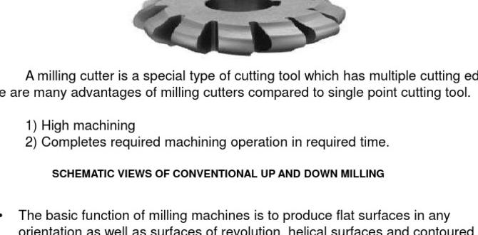
Unlike flat-bottomed end mills, a ball nose end mill has a perfectly rounded cutting tip. This shape is fantastic for creating curved surfaces, pockets with rounded corners, and 3D contours. For roughing, its rounded profile allows for smoother engagement with the material, which can help reduce chatter and improve the surface finish compared to a sharp-cornered tool.
What is TiAlN Coating?
TiAlN stands for Titanium Aluminum Nitride. This is a super-hard coating applied to the surface of the end mill. It provides several benefits, especially important when cutting materials like plastic:
- Heat Resistance: TiAlN can withstand very high temperatures, which is crucial because machining plastics can generate significant heat. This coating helps prevent the end mill from getting too hot, reducing the risk of melting the HDPE.
- Reduced Friction: The smooth, hard surface of the coating minimizes friction between the tool and the workpiece. Less friction means less heat buildup and a cleaner cut.
- Increased Tool Life: By resisting heat and wear, TiAlN coatings significantly extend the lifespan of the end mill, meaning you can cut more material before needing to replace it.
- Improved Chip Evacuation: The coating can help chips flow off the cutting edges more easily, preventing them from packing up in the flutes and causing issues.
The “40 Degree” Aspect (and why it matters for roughing)
When we talk about a “40-degree TiAlN ball nose end mill for HDPE roughing,” the “40-degree” often refers to the helix angle of the flutes. A steeper helix angle (like 40 degrees or more) can offer:
- Smoother Cutting Action: It allows for a more shearing cut, which is generally better for softer materials like plastics. This leads to less vibration and a cleaner chip.
- Better Chip Evacuation: The steeper angle helps to pull chips away from the cutting zone more effectively, preventing material buildup.
- Reduced Cutting Forces: Sometimes, a higher helix angle can result in lower forces required to cut the material, which is beneficial for your machine and workpiece.
While very steep helix angles (like 45 or 60 degrees) are often recommended for plastics, a 40-degree angle still provides a good balance of performance for many HDPE roughing applications. The combination of the ball nose tip, the TiAlN coating, and the helix angle makes this tool a specialized powerhouse for tackling HDPE.
Choosing the Right TiAlN Ball Nose End Mill for HDPE
Not all end mills are created equal, and for HDPE roughing, a few specifications are important when selecting your TiAlN ball nose end mill:
Key Specifications to Look For:
- Diameter: This will depend on the size of your project and the capabilities of your milling machine. Larger diameters remove material faster but require a more powerful machine.
- Number of Flutes: For plastics, 2-flute or 3-flute end mills are often preferred. More flutes can lead to finer finishes but can cause melting issues in plastics because chips don’t have enough space to escape. 2-flute is generally a safe bet for roughing softer plastics like HDPE.
- Coating: As discussed, TiAlN is excellent. Look for other high-performance coatings like ZrN (Zirconium Nitride) or specialized plastic coatings if available, but TiAlN is a great all-around choice.
- Material: High-speed steel (HSS) end mills are more affordable but wear faster. Carbide end mills are harder, stay sharper longer, and are generally recommended for better performance and longevity, especially with coatings.
- Helix Angle: As mentioned, 40 degrees is good, but 45 or 60 degrees can be even better for plastics if available.
Where to Find Authoritative Information
When in doubt about tool selection, consulting resources from reputable tooling manufacturers or industrial supply companies can be very helpful. For example, many leading tool manufacturers provide detailed catalogs and application guides. You might also find valuable information on material machining databases, such as those provided by organizations like The Association For Manufacturing Technology (AMT), which often detail best practices for machining various materials.
Setting Up Your Milling Machine for HDPE Roughing
Before you even touch the machine, proper setup is key. This ensures safety and the best possible results.
Essential Machine Checks:
- Rigidity: Make sure your milling machine is sturdy and all its components are tightened. Any play or vibration can lead to poor cuts and tool breakage in plastics.
- Spindle Cleanliness: Ensure the spindle taper and tool holder are clean and free of debris. A secure tool in the spindle is paramount.
- Workholding Security: Your piece of HDPE must be clamped down firmly. Use high-quality clamps and ensure they won’t interfere with the tool path. A slipping workpiece is a serious safety hazard and will ruin your part.
Tool Holder and Collet Selection:
Use a high-quality tool holder and collet. A tool holder with good runout (how perfectly the tool spins) is essential for clean cuts. For plastics, it’s often best to use collets that provide good gripping force without crushing the tool shank. Ensure the collet and holder are the correct size for your end mill shank.
Safe Machining Parameters for HDPE
This is where we bridge the gap between what makes the tool work and how to use it without issues. Getting the speeds and feeds right is critical for HDPE. These parameters are often a starting point and may need adjustment based on your specific machine, the exact grade of HDPE, and the tool.
Speeds and Feeds Explained (Simply!)
- Spindle Speed (RPM): This is how fast the end mill spins. For HDPE, you generally want a higher spindle speed. This helps the cutting edges slice through the material efficiently rather than scrubbing and generating excessive heat.
- Feed Rate (IPM or mm/min): This is how fast the tool moves through the material. You want a feed rate that’s fast enough to create a chip and prevent melting, but not so fast that it overloads the tool or machine.
- Chip Load: This is the thickness of the material being removed by each cutting edge of the end mill. A good chip load is crucial for effective material removal and preventing melting.
Recommended Starting Parameters for HDPE Roughing:
These are general guidelines. Always consult your tool manufacturer’s recommendations if available. A common starting point for a 1/4″ or 1/2″ diameter TiAlN ball nose end mill on HDPE might look like this:
Important Note: ALWAYS wear safety glasses and appropriate PPE (Personal Protective Equipment) when operating any milling machine. HDPE chips can be sharp and fly unexpectedly.
| End Mill Diameter | Spindle Speed (RPM) | Feed Rate (IPM) | Chip Load (per tooth) ≈ | Depth of Cut (DOC) | Width of Cut (WOC) |
|---|---|---|---|---|---|
| 1/8″ (3mm) | 8,000 – 12,000 | 15 – 30 | 0.001″ – 0.002″ | 0.030″ – 0.060″ | 0.050″ – 0.100″ (or 50% of diameter) |
| 1/4″ (6mm) | 6,000 – 10,000 | 30 – 60 | 0.002″ – 0.003″ | 0.060″ – 0.125″ | 0.100″ – 0.250″ (or 50% of diameter) |
| 1/2″ (12mm) | 4,000 – 8,000 | 60 – 120 | 0.003″ – 0.005″ | 0.125″ – 0.250″ | 0.250″ – 0.500″ (or 50% of diameter) |
Table Key:
- IPM: Inches Per Minute
- DOC: Depth of Cut (how deep the tool cuts into the material)
- WOC: Width of Cut (how much of the tool’s diameter is engaged in the cut sideways)
Adjusting Parameters for Success: The “Listen and Look” Method
- If it’s melting: Increase feed rate or spindle speed. Reduce depth of cut. Ensure good chip evacuation.
- If it’s chattering (making a noisy vibration): Reduce feed rate or spindle speed. Increase depth of cut slightly (sometimes a deeper cut is more stable). Make sure your machine is rigid and the tool is held securely.
- If chips are small dust particles: Increase chip load (feed rate relative to spindle speed) or reduce depth/width of cut.
- If chips are large and stringy: Reduce feed rate or increase spindle speed.
The TiAlN coating helps immensely with heat, but you still need to manage it. Often, a light mist of coolant or compressed air directed at the cutting zone can help further dissipate heat and clear chips. For HDPE, some machinists prefer not to use liquid coolant as it can sometimes mix with fine plastic particles to form a slurry. Compressed air is often a cleaner, safer choice.
Step-by-Step: Roughing HDPE with Your TiAlN Ball Nose End Mill
Now that your machine is ready and you have a good idea of the parameters, let’s walk through the process. Remember, safety first, always!
Step 1: Secure the Workpiece
Place your HDPE block on the milling machine table. Use multiple sturdy clamps to ensure it cannot move. Check that the clamps won’t be hit by the end mill during the operation.
Step 2: Install the End Mill
Insert the TiAlN ball nose end mill into the appropriate collet and tighten it securely in the spindle. Ensure the shank is properly seated in the collet and the collet is tightened in the spindle. Double-check it’s seated correctly by giving it a gentle pull.
Step 3: Set Your Zero Point (Origin)
Use your machine’s control system or a dial indicator to set the X, Y, and Z zero points. For the Z-axis, it’s common practice to “touch off” on the top surface of your workpiece. Be precise!
Step 4: Program Your Tool Path (or Manually Control)
If using a CNC mill, you’ll typically program a roughing tool path using CAM software. Ensure the software knows you are using a ball nose end mill and that it is set to the correct diameter. For manual milling, you will carefully guide the machine through your desired cuts using the handwheels.
Step 5: Apply Initial Cutting Parameters
Enter your planned spindle speed and feed rate into the machine control. Double-check these against your chosen starting parameters. If using air blast or mist coolant, turn it on before starting.
Step 6: Perform a Dry Run (Optional but Recommended)
Before cutting into the HDPE, jog the machine through the tool path with the spindle off to ensure there are no collisions and everything looks correct. Some CNC controls have a built-in simulation mode for this.
Step 7: Start the Cut
Turn on the spindle and then slowly engage the feed rate to start cutting into the HDPE. Observe the cutting action closely.
Step 8: Monitor and Adjust
Listen to the sound of the cut. Watch the chips being produced. Are they melting? Are they flying cleanly? Is the machine vibrating excessively? Adjust spindle speed or feed rate as needed based on the “Listen and Look” method described earlier. If you’re reducing the depth of cut, do that incrementally.
Step 9: Complete Roughing Passes
Continue making passes, removing material until you are close to your final desired shape. Remember that roughing is about bulk removal, so it’s okay if the surface finish isn’t perfect at this stage. You’ll refine it later with finishing passes.
Step 10: Clean Up and Inspect
Once roughing is complete, turn off the spindle and feed. Carefully remove the workpiece and inspect it. Clear any residual chips from the machine table and the workpiece.
Common Pitfalls and How to Avoid Them
Even with the right tool, mistakes can happen. Here are some common issues when machining HDPE and how to sidestep them:
- Melting/Gooey Chips:
- Cause: Too much friction, not enough chip load, or spindle speed too low for feed rate.
- Solution: Increase feed rate, increase spindle speed, reduce depth/width of cut, ensure good chip evacuation (using air blast helps!). A higher helix angle tool can also help.
- Tool Breakage:
- Cause: Feed rate too high, depth of cut too aggressive, worn tooling, loose workpiece, or excessive vibration.
- Solution: Reduce feed and depth of cut. Ensure workpiece is firmly clamped. Use sharp tooling. Check for and eliminate machine play or vibration.
- Poor Surface Finish:
- Cause: Dull tool, incorrect speeds/feeds, excessive vibration, or material inconsistencies.
- Solution: Use a sharp, high-quality end mill. Dial in your speeds and feeds, aiming for a consistent chip load. Ensure machine rigidity and secure workholding. For a better finish, reduce the depth of cut and width of cut for subsequent passes after roughing.
- Work Creep (Workpiece Moving):
- Cause: Insufficient clamping force or improperly positioned clamps.
- Solution: Re-evaluate your workholding strategy. Use more clamps if necessary and ensure they are positioned to resist the cutting forces.
Finishing Passes After Roughing
Once you’ve completed your roughing passes with


