A 45-degree Tialn ball nose end mill is essential for cast iron contouring because its specific geometry and coating allow for efficient, smooth material removal, preventing tool wear and providing excellent surface finish in this challenging material.
Hey there, machinist friends! Daniel Bates here from Lathe Hub. Ever look at a piece of cast iron and think, “How am I going to shape this beautifully?” It can seem pretty tough, right? That’s where the right tools make all the difference. Today, we’re diving into a special kind of tool: the 45-degree Tialn ball nose end mill. It might sound a bit technical, but I promise, it’s surprisingly straightforward and a real game-changer for getting those smooth, flowing shapes in cast iron. We’ll break down exactly why this tool is so good at its job and how you can use it to get fantastic results.
Why Cast Iron is a Challenge
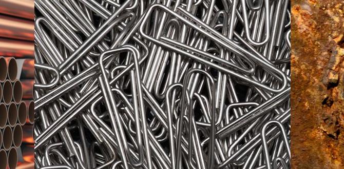
Cast iron, while incredibly useful for its durability and vibration-dampening qualities, presents unique challenges when you’re trying to machine it, especially for contouring work. It’s not as soft as some plastics, nor as forgiving as mild steel. Cast iron’s microstructure, containing graphite flakes or nodules, can lead to abrasive wear on cutting tools. This means standard tools can dull quickly, leave a rough finish, or even chip. For intricate contouring – those smooth, curved surfaces – you need a tool that can handle this abrasive nature while producing a clean cut. Without the right setup, you can end up with frustrated attempts and poor results.
Introducing the 45-Degree Tialn Ball Nose End Mill
So, what makes this specific tool so special for cast iron contouring? Let’s break down its name:
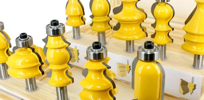
- Ball Nose: This refers to the shape of the cutting tip. A ball nose end mill has a hemispherical tip. This is crucial for contouring because it allows you to create smooth, rounded surfaces and fillets without leaving sharp corners. It’s like using a round pen to draw a curve versus a square one.
- 45 Degree: This angle relates to the helix angle of the flutes. A 45-degree helix angle offers a good balance between aggressive material removal and a smooth surface finish. It’s not as steep as a high-helix mill (which might chip brittle cast iron) and not as shallow as a low-helix mill (which might chatter or leave a rougher finish). This specific angle is often cited as optimal for contouring operations in various materials, including cast iron, by providing good chip evacuation and reducing cutting forces.
- Tialn Coating: This is perhaps the most critical component for tackling cast iron. Tialn stands for Titanium Aluminum Nitride. It’s a multi-layer PVD (Physical Vapor Deposition) coating applied to the carbide tool. Tialn is renowned for its incredible hardness, high thermal stability, and excellent lubricity. When machining cast iron, which can be abrasive and generate heat, the Tialn coating acts as a shield. It drastically reduces friction, prevents the workpiece material from sticking to the tool (which is called built-up edge, or BUE), and protects the carbide substrate from excessive heat and wear. This means your tool stays sharper for longer and can cut cleaner.
Together, these features make the 45-degree Tialn ball nose end mill a powerhouse for achieving precise, smooth, and efficient contours in cast iron. It’s designed to tackle the material’s toughness and abrasiveness head-on.
How It Works for Cast Iron
Think of machining as a delicate dance between your cutting tool and the workpiece. Cast iron, as we’ve discussed, can be a bit of a clumsy dance partner. Here’s how the 45-degree Tialn ball nose end mill is specifically suited:
Managing Heat and Friction
Cast iron contains graphite, which can act like a lubricant in some scenarios. However, the friction generated during high-speed machining can also lead to rapid tool wear and heat buildup. The Tialn coating is key here. Its ultra-hard surface resists wear, while its ceramic-like properties reduce friction. This means less heat is generated at the cutting edge, preserving the tool and allowing for faster, more efficient cuts. This is especially important when doing continuous contouring, where the tool is in contact with the material for extended periods.
Preventing Tool Chatter and Vibration
Chatter, that annoying vibration that results in a rough, wavy surface finish, is a common enemy in machining. The 45-degree helix angle helps to mitigate chatter. A steeper helix angle (like 45 degrees) provides a more gradual engagement of the cutting edge with the material. This results in a smoother, shearing-type cut rather than a more abrupt impact. This quieter, more stable cut is essential for achieving the smooth, flowing surfaces required for contouring, especially on a material like cast iron that can be brittle.
Achieving Smooth Surface Finishes
The ball nose geometry inherently lends itself to creating smooth, blended surfaces. When you’re contouring, the rounded tip of the end mill follows the programmed path, allowing you to generate fillets, radii, and complex organic shapes without the need for multiple passes with different tools or extensive post-machining finishing. The Tialn coating further enhances this by ensuring a clean cut with minimal tearing or material buildup, leaving behind an excellent surface finish straight off the mill.
Optimizing Chip Evacuation
Effective chip removal is vital in any machining operation. If chips jam up in the flutes, they can recut, leading to poor surface finish, increased tool wear, and even tool breakage. The 45-degree helix angle, combined with the design of the flutes, strikes a good balance for chip evacuation. It’s aggressive enough to break chips into manageable pieces but not so steep that it creates excessive cutting pressure or hinders chip flow, which is a concern for some coatings when dealing with abrasive materials.
Key Features to Look For
While the “45-degree Tialn ball nose end mill” is quite specific, there are still variations and features that can make one tool better than another for your cast iron contouring needs. Always check the specifications before purchasing:
- Carbide Grade: The underlying material of the end mill is usually tungsten carbide. Higher-quality carbide grades with finer grain structures offer better strength and toughness, which are crucial for resisting chipping.
- Number of Flutes: For contouring in cast iron, a 2-flute or 3-flute end mill is generally recommended.
- 2 Flutes: Excellent for contouring as they provide good chip clearance and are less prone to clogging. They can often run at higher speeds and feed rates in softer materials, but for cast iron, they offer a good balance for smooth cutting.
- 3 Flutes: Offer a bit more rigidity and a smoother finish than 2-flutes. They can be a good choice if chatter is a significant concern or if you need to achieve a very fine surface finish.
- Coating Thickness and Quality: The Tialn coating is applied through PVD. The thickness and uniformity of this coating are critical for its performance. Reputable manufacturers invest in high-quality coating processes.
- Overall Length and Neck Relief: Consider the depth of your contours and the clearance needed in your workpiece geometry. Some end mills have a neck relief, which is a portion of the shank that is reduced in diameter. This allows the tool to reach deeper into cavities or around features without the shank colliding with the workpiece.
- Diameter: Choose a diameter appropriate for the size of the radii and contours you need to create. Small ball noses are great for intricate details, while larger ones are better for broader sweeping curves.
Setting Up Your Mill for Cast Iron Contouring
Getting the right tool is only half the battle. Proper setup on your milling machine is crucial for success and safety, especially when dealing with cast iron. Think of this as preparing your workspace and your machine for the task.
1. Secure the Workpiece (Vise or Fixture)
Cast iron can be heavy and may require sturdy clamping. Ensure your workpiece is securely held in a vise or a dedicated fixture. A loose workpiece is a major safety hazard and will lead to poor machining results. Use appropriate jaws for your vise if necessary. For irregular shapes, consider using specialized fixturing to support the part evenly.
2. Choose Your Coolant/Lubricant
While some take a dry approach, using a coolant or lubricant is highly recommended when machining cast iron. It helps to:
- Cool the cutting edge: Reduces heat buildup on the tool.
- Lubricate the cut: Reduces friction and improves surface finish.
- Flush away chips: Prevents chip recutting and buildup.
For cast iron, a flood coolant system with a water-soluble oil or a synthetic coolant is often a good choice. Some machinists also use specialized spray mists or even air blasts, but flood coolant generally provides superior cooling and chip evacuation. Always use a coolant that is marked as suitable for cast iron. Safety note: ensure your machine is designed to handle coolants, and wear appropriate protective gear, like safety glasses and splash guards.
3. Machine Settings: Speeds and Feeds
This is where we translate the tool’s capabilities into actual cutting parameters. Speeds and feeds are interdependent and influence the chip load, surface finish, and tool life. For a 45-degree Tialn ball nose end mill in cast iron, you’ll generally want to start with conservative settings and adjust as needed.
Here’s a typical range to start with. These are guidelines, and your specific machine, the exact grade of cast iron, and the tool manufacturer’s recommendations will dictate the best values:
| Tool Diameter | Spindle Speed (RPM) | Feed Rate (IPM) | Chip Load per Flute (inch) |
|---|---|---|---|
| 1/4″ (6mm) | 2000 – 4000 | 8 – 16 | 0.001 – 0.002 |
| 1/2″ (12mm) | 1500 – 3000 | 15 – 30 | 0.0015 – 0.0025 |
| 3/4″ (20mm) | 1000 – 2500 | 20 – 40 | 0.002 – 0.003 |
Understanding the terms:
- Spindle Speed (RPM): How fast the tool rotates.
- Feed Rate (IPM): How fast the tool moves through the material.
- Chip Load per Flute: The thickness of the material removed by each cutting edge per revolution. This is a critical parameter. Aim for a chip load that is neither too thin (which causes rubbing and tool wear) nor too thick (which can overload the tool).
For contouring, especially with a ball nose, you often run the tool at a smaller step-over (the distance the tool moves sideways between passes) and potentially a shallower depth of cut to achieve a good surface finish. The feed rate is often adjusted to maintain the desired chip load.
Depth of Cut and Stepover
Depth of Cut: For contouring, you’re typically removing material in layers as the tool follows the programmed path. The depth of cut will depend on the specific operation and the machine’s rigidity. For roughing passes, you can take a more aggressive cut (e.g., 0.050″ to 0.100″ deep for a 1/2″ tool). For finishing passes, you’ll want a very shallow depth of cut (e.g., 0.005″ to 0.010″) to ensure a smooth surface finish.
Stepover: This is the distance the cutter moves sideways between parallel passes. For contouring, a smaller stepover (e.g., 10-25% of the tool diameter) will result in a smoother surface finish because the scallops left by the tool are less pronounced and blend together better.
4. Tool Holder and Runout
Use a high-quality tool holder – a collet chuck or a precisely ground chuck. Minimal runout (wobble) is crucial. Excessive runout will lead to inconsistent cutting, poor surface finish, and premature tool wear. Ensure your tool is seated correctly and tightened properly.
Step-by-Step Cast Iron Contouring with Your End Mill
Ready to put your 45-degree Tialn ball nose end mill to work? Here’s a general process. Remember to always follow proper safety procedures for your milling machine.
Step 1: Program Your Toolpath
Using your CAD/CAM software (or by manual programming), define your desired contour. This will involve creating toolpaths that guide the ball nose end mill around the shape. For smooth contours, you’ll typically use 3D contouring or surface milling strategies. Ensure your software is set up with the correct tool diameter and type.
Step 2: Set Up the Machine and Workpiece
As discussed in the setup section, securely clamp your cast iron workpiece. Make sure your chosen coolant system is ready to go.
Step 3: Load and Zero the Tool
Carefully insert the 45-degree Tialn ball nose end mill into your collet chuck or tool holder. Tighten it securely. Use your machine’s probing system or an edge finder to accurately set your X, Y, and Z zero points relative to the workpiece. For Z-zero, typically set it at the top surface of the workpiece.
Step 4: Perform a Dry Run or Air Cut
Crucially, before cutting into your valuable cast iron, perform an “air cut.” This means running the program with the spindle off or with the tool well above the workpiece. Watch the tool move through its entire programmed path. This helps you:
- Verify the tool path is correct.
- Check for any potential collisions or crashes.
- Ensure the machine movements are as expected.
Step 5: Make the First Cut (Roughing)
With the tool in position and coolant flowing, start the program. For the initial passes, you’ll be establishing the basic shape. If your toolpath includes roughing and finishing passes:
- Roughing: Take deeper cuts to remove the bulk of the material. The 45-degree angle combined with the Tialn coating should handle this efficiently.
- Monitor: Listen to the sound of the cut and observe the chips being produced. If it sounds “grindy” or you see small, powdery chips, your feed rate might be too low or your depth of cut too high for the current settings. If it’s smooth and producing distinct chips, you’re likely in a good zone.
Step 6: Perform Finishing Passes
After the roughing passes, the toolpath will transition to finishing. This involves:
- Shallower Depth of Cut: Significantly reduce the depth of cut (e.g., 0.005″ – 0.010″) to achieve a smooth surface.
- Smaller Stepover: Use a tighter stepover percentage for blending the tool paths.
- Consistent Feed Rate: Maintain a consistent feed rate to ensure a uniform surface finish.
The ball nose will glide along the surface, leaving behind a beautiful, smooth contour. The Tialn coating is vital here, preventing any sticking and ensuring the sharp edges of the ball nose create a clean, accurate profile.
Step 7: Inspect and Clean
Once the program is complete, turn off the spindle and coolant. Carefully inspect the contoured surface for finish quality, accuracy,