Tialn Ball Nose End Mill 45 Degree: Your Go-To for Precise Profiling
The Tialn ball nose end mill with a 45-degree helix angle is an excellent tool for beginning machinists tackling profiling operations, especially on materials like aluminum 7075. Its design allows for smooth cutting, reduces chatter, and is very forgiving for those new to milling. Let’s break down how to use this workhorse for your profiling needs.
Hey there, fellow makers and machinists! Daniel Bates here from Lathe Hub. Ever stare at a blueprint or a part you need to create, and feel a little overwhelmed by how to make those curved edges or intricate outlines? You’re not alone. Profiling, which is essentially shaping the outer contour of a workpiece, can seem tricky, especially with fancy cutters like ball nose end mills. But what if I told you there’s a specific type of tool that makes this process much easier for beginners? That’s where the Tialn ball nose end mill with a 45-degree helix angle comes in. It’s designed to cut smoothly, especially in common materials like aluminum. We’re going to walk through exactly how to use this fantastic tool to achieve clean, precise profiles, making your projects look professional without the high-level stress.
We’ll cover everything from understanding why this specific tool is so beginner-friendly to setting it up on your machine and making those first cuts. Get ready to boost your confidence and your machining skills!
What is a Ball Nose End Mill and Why 45 Degrees?
Before we dive into the “how-to,” let’s quickly understand what we’re working with. A ball nose end mill, as the name suggests, has a cutting tip in the shape of a ball. This shape is fantastic for creating rounded features, fillets, and importantly for us, smooth, continuous profiles. Unlike flat-bottomed end mills, the ball nose allows for a seamless transition around curves and corners.
Now, about that “45-degree” part. This refers to the helix angle of the flutes (the spiral grooves on the cutter). A 45-degree helix angle provides a good balance for many materials. It offers a relatively aggressive cut compared to higher helix angles (like 60 or 90 degrees), which means it can remove material efficiently, but it’s also gentler than very low helix angles. This intermediate angle helps to:
- Reduce Vibration and Chatter: The gradual engagement of the cutting edge due to the 45-degree angle leads to smoother cuts and less noise from your machine. This is a huge win for beginners, as chatter can ruin a surface finish.
- Improve Chip Evacuation: The spiral flutes help to efficiently clear chips away from the cutting zone. Good chip evacuation is crucial to prevent the tool from overheating or becoming clogged, which can lead to tool breakage.
- Versatility: It can handle a good range of materials, including softer metals like aluminum (especially tougher alloys like 7075) and plastics, as well as some steels.
When you combine the ball nose shape with the 45-degree helix, you get a tool that’s forgiving, efficient, and capable of producing excellent surfaces. It’s a real workhorse for profiling tasks, especially when you’re learning the ropes.
Why Choose a Tialn Coating?
You might have seen “TiAlN” mentioned. This stands for Titanium Aluminum Nitride. It’s a thin, hard coating applied to the end mill that offers several benefits, especially when cutting tougher materials or at higher speeds:
- Increased Hardness: Makes the tool more resistant to wear, meaning it stays sharp for longer.
- Higher Heat Resistance: The coating forms a barrier that helps dissipate heat, allowing for faster cutting speeds and preventing the tool from softening.
- Reduced Friction: Helps chips slide off the cutter more easily, further improving chip evacuation and reducing heat buildup.
- Good for Difficult Materials: Especially beneficial for materials like aluminum alloys (like 7075), stainless steels, and other harder metals where heat and friction can be significant issues.
For profiling aluminum 7075, a TiAlN coating on your 45-degree ball nose end mill can significantly improve tool life and the quality of your finish. It’s an investment that pays off in smoother cuts and fewer broken tools.
Essential Tools and Setup Checklist
Before you grab your Tialn ball nose end mill and start cutting, let’s make sure you have everything you need and your machine is ready. Safety and proper setup are paramount for success and avoiding frustration.
What You’ll Need:
- Tialn Ball Nose End Mill (45-Degree Helix): The star of our show! Ensure it’s the correct diameter for your needs.
- Collet Chuck or Tool Holder: A good quality one that can hold the end mill securely and run true. For CNC machines, a shrink-fit holder or a high-precision collet chuck is ideal to minimize runout.
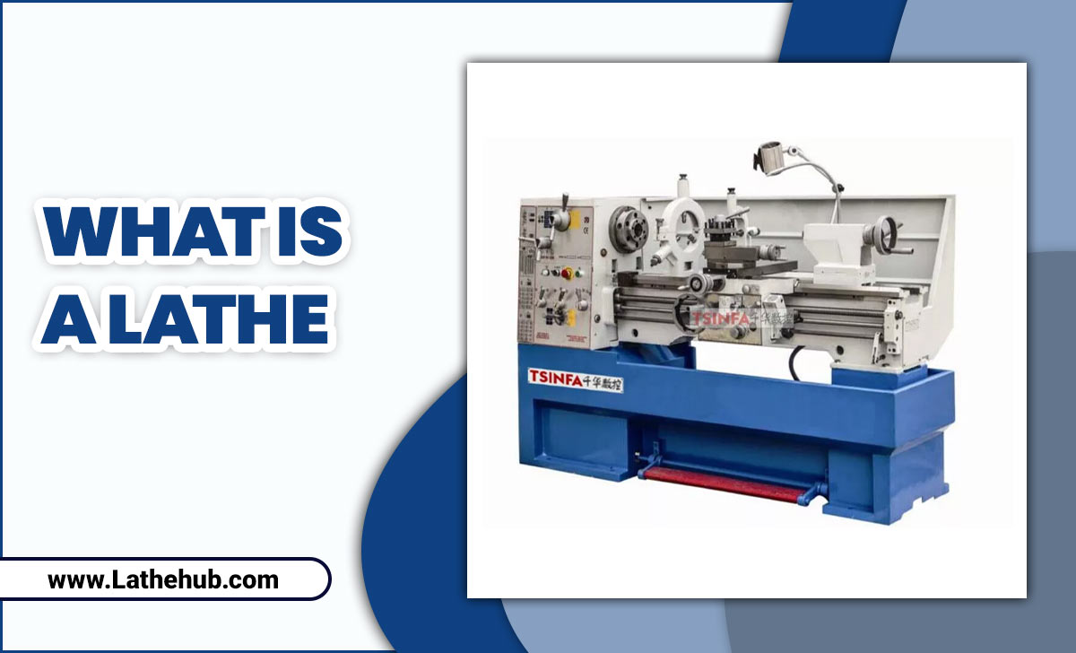
- Milling Machine: Whether it’s a manual mill, a CNC, or even a robust rotary tool with appropriate attachment.
- Workholding: This is critical. You need to securely clamp your workpiece (e.g., aluminum 7075 block) to the machine table. Vises, fixture plates, or specialized clamps are common. Ensure your material won’t move AT ALL during the cut.
- Cutting Fluid or Lubricant: Essential for aluminum to prevent chips from welding to the cutter and to keep things cool. Compressed air can also be used for chip blow-off.
- Depth Micrometer or Caliper for Z-Zeroing: To accurately set your tool’s height relative to the workpiece.
- Safety Glasses and Face Shield: Non-negotiable. Always protect your eyes.
- Hearing Protection: Milling can be loud.
- Gloves: For handling material and tools, but be cautious around moving machinery.
- Machine Lubrication and General Maintenance Checklist: A well-maintained machine is safer and more predictable. Check that your coolant system is working, and there are no obvious leaks or damaged parts.
Machine Setup Checklist:
1. Clean Work Area: Ensure the machine table and your workholding device are free of debris.
2. Secure Workpiece: Clamp your aluminum 7075 block firmly. Make sure it’s indicated to be square if necessary for your project. Double-check that it cannot shift.
3. Insert End Mill: Carefully install the Tialn ball nose end mill into your collet chuck or tool holder. Ensure it’s seated correctly and tightened securely. Minimize the amount of tool sticking out past the collet to reduce deflection.
4. Mount Tool Holder: If using a separate tool holder (like an R8 or CAT taper), securely mount it into the milling head.
5. Set Spindle Speed (RPM): This depends heavily on your material, the end mill diameter, and your machine’s capabilities. For aluminum, you generally want higher RPMs than for steel. A good starting point for a 1/4″ or 1/2″ ball nose end mill in aluminum 7075 might be anywhere from 5,000 to 20,000 RPM. Always consult a manufacturer’s chart or calculate your Surface Feet Per Minute (SFM) and convert it to RPM: RPM = (SFM × 3.819) / Diameter.
6. Set Feed Rate: This is how fast the tool moves through the material laterally. Too fast, and you’ll break the tool or overload the machine. Too slow, and you’ll rub and generate excessive heat. For aluminum profiling with a ball nose end mill, a feed rate that allows for a good chip load is key. Chip load is the thickness of the chip being produced. A common guideline is: Feed per Tooth (IPT) = (Desired Chip Load) × Number of Flutes, then Feed Rate (IPM) = IPT × RPM × Number of Flutes. For rough estimates on aluminum, aim for a chip load between 0.001″ and 0.005″ depending on tool diameter and rigidity.
7. Set Cutting Depth (Z-Axis): This is the depth of material the end mill will remove in a single pass. For profiling, you’ll often be cutting the outline of your part at a specific depth. Start with conservative depths, especially in aluminum, to avoid tool overload. For profiling, you might take multiple passes to reach the final desired depth.
8. Establish Z-Zero: This is crucial. Carefully touch the tip of the ball nose end mill to the top surface of your clamped workpiece. Then, set your machine’s Z-axis DRO (Digital Readout) or your CAM software’s work offset to zero. Alternatively, use a depth micrometer on the quill after touching off.
9. Set X and Y Zero/Work Offset: Define your starting point in the X and Y directions for your profiling path. This is often the center of your part, an edge, or a specific datum point defined in your design.
10. Coolant/Lubrication: Ensure your coolant or lubrication system is ready to go. For aluminum, a mist coolant or a flood coolant system is highly recommended. If using compressed air, set it up to blow chips away from the cutting zone.
Step-by-Step: Profiling with Your Tialn Ball Nose End Mill
Now, let’s get cutting! Profiling involves cutting the exterior of a shape. For beginners, using your Tialn ball nose end mill for this task is often done during the finishing pass, or sometimes as a single pass if the material is thin and the tool is robust. Let’s assume you’re cutting the outer profile of a part to its final dimensions.
Method 1: Manual Milling (Handwheel Control)
This method requires a steady hand and good feel for the machine. It’s excellent for simple shapes or for learning the fundamentals.
Step 1: Tool Engagement Strategy
When profiling manually, you’ll be feeding the material into the rotating end mill. There are two main ways to do this, and for beginners, it’s often safer and produces a better finish to use “climb milling” where possible, but be cautious. For manual milling, especially in aluminum, conventional milling is often safer as it prevents the cutter from “grabbing” the workpiece and potentially throwing it or breaking the tool. However, climb milling can yield a superior finish if done correctly and with a very rigid setup.
Conventional Milling (Generally Safer for Manual): The workpiece moves against the rotation of the cutter. The cutter “climbs” up the material. You’ll feed the workpiece into the cutter.
Climb Milling: The workpiece moves with the rotation of the cutter. The cutter “falls” into the material. You’ll feed the workpiece away from the cutter as it rotates downwards.
Recommendation for Beginners on Manual Mills: Start with conventional milling. Feed your X or Y axis slowly and steadily into the rotating end mill, watching for chip formation and listening to the cut. Ensure your handwheels have minimal backlash for smooth feeding.
Step 2: Setting Up the Cut Path
You’ll typically need to define your path using your DROs or by visual referencing. For simple shapes, you might use a center finder or edge finder to locate your starting point.
Step 3: Making the First Pass
- Engage Spindle: Start your spindle at the calculated RPM.
- Apply Cutting Fluid: Ensure coolant is flowing or misting.
- Approach the Material: Slowly bring the rotating end mill towards your workpiece until it’s just about to touch the edge you want to profile.
- Set Z-Depth: Lower the tool to your desired cutting depth (or prepare for your first pass at a shallow depth).
- Initiate Feed: Using the appropriate handwheel (X or Y, depending on your path), begin feeding the workpiece into the end mill at a slow, consistent rate. Your goal is to remove material evenly, creating chips.
- Observe and Listen: Pay close attention to the sound of the cut and the appearance of the chips. A consistent, light “sizzle” or “shaving” sound is good. A harsh grinding or chattering sound means something is wrong – speed, feed, depth, or rigidity issue.
- Complete the Profile: Continue feeding along your desired path, making sure to maintain a smooth, continuous motion. For corners, you’ll need to carefully turn your handwheels to follow the contour. The ball nose will naturally create a rounded corner if you feed smoothly around it.
- Retract Tool: Once the entire perimeter is cut, carefully raise the Z-axis and then move the mill head away from the workpiece.
Step 4: Multiple Passes (If Necessary)
If your initial depth is too much for a single pass, or if you’re using a roughing step followed by a finishing step:
- Roughing Pass: Take a deeper cut, leaving a small amount of material (e.g., 0.010″ – 0.020″) for a finishing pass.
- Finishing Pass: After retracting, simply run the exact same path again, but this time at your final desired depth. This second pass will clean up any imperfections left by the roughing pass and provide a superior surface finish – perfect for that ball nose.
Method 2: CNC Milling
CNC provides automated precision, turning your design into reality with programmed movements. The Tialn ball nose end mill is fantastic for CNC profiling.
Step 1: CAM Programming
This is where you’ll define the toolpath. Using CAM (Computer-Aided Manufacturing) software, you’ll:
- Import Your CAD Model: Load your 2D or 3D design.
- Select the Tool: Define your Tialn ball nose end mill in the software, including its diameter, number of flutes, and any coatings if the software has advanced libraries.
- Choose a Strategy: Select a “2D Contour” or “Profile” operation.
- Define Cutting Parameters: Input your calculated RPM, feed rate, chip load, and step-down (depth of pass). For profiling, you’ll usually have a “Stepover” set to 0% for a single pass, or a very small value if you’re doing a multi-pass profile to ensure the cleanest edges.
- Set Heights: Define your clearance plane, retract plane, and the final Z-depth of cut.
- Assign Work/Tool Offsets: Ensure your X, Y, and Z zero points (or G54, G55, etc., work offsets) are correctly set on the CNC machine to match your CAM setup.
- Generate Toolpath: The software will create the G-code.
- Simulate: CRITICAL STEP! Always run a simulation in your CAM software to visually check the toolpath for any collisions, gouges, or incorrect movements.
Step 2: Machine Setup & Tool Loading
- Mount Workpiece: Securely clamp your aluminum 7075 in the CNC vise or fixture.
- Load End Mill: Insert the Tialn ball nose end mill into the appropriate tool holder and load it into the CNC spindle.
- Set Tool Length Offset (TLO): Use a tool setter or touch off to accurately measure the length of the tool and record it in the machine’s offset table.
- Set Work Coordinate System (WCS): Home the machine, jog to your defined origin point (X0, Y0, Z0), and set your G54 (or other active) work offset.
Step 3: Running the CNC Program
- Dry Run: Perform a “dry run” with the spindle off, but the machine moving through the G-code at a reduced feed rate. Watch to ensure the toolpath stays clear of clamps and obstructions.
- First Pass (Optional but Recommended): If possible, run a very shallow first pass (e.g., 0.005″ deep) to confirm the positioning and the cutting action.
- Enable Coolant/Air Blast: Turn on your lubrication or air blast system.
- Start Spindle: Engage the spindle at the programmed RPM.
- Execute Program: Start the G-code program. The CNC will automatically move the tool to profile your part.
- Monitor: Keep an eye on the cutting process, listening for any unusual sounds and checking chip formation.
- Part Completion: Once the program finishes, the spindle will stop, and the tool will retract. You can then remove the finished part.
For profiling aluminum 7075, using a ball nose end mill ensures that even small internal radius corners will be properly formed according to your design, and the outer profile will have a smooth, continuous curvature.