The world of metalworking can seem complex, but it can be fascinating too. Have you ever wondered how tools are powered in a metal lathe? Understanding the tool post metal lathe wiring diagram can help you unlock that mystery.
Imagine stepping into a workshop filled with the sounds of whirring machines. You see a skilled craftsman transforming raw metal into beautiful shapes. Have you noticed how precise they are? A lot of that precision comes from the wiring in their machines.
Many people don’t realize how important wiring is in a metal lathe. It connects the motor, controls, and tool post. Without a good wiring diagram, you might struggle to get everything working. Did you know that even a small error can lead to big problems?
This article will take you through the basics of the tool post metal lathe wiring diagram. You’ll learn how each part connects and why they matter. By the end, you’ll have a clearer picture of how to make your metal lathe run smoothly.
Tool Post Metal Lathe Wiring Diagram: A Comprehensive Guide

Understanding Tool Post Metal Lathe Wiring Diagrams
Tool post metal lathe wiring diagrams are essential for safely connecting and operating machinery. They show you how to link components, ensuring the lathe works correctly. Did you know that clear wiring can prevent accidents? Knowing the wiring layout can also help you troubleshoot problems faster. If you’re a DIY enthusiast or a professional, grasping these diagrams can enhance your skills. Explore how organized wiring leads to smoother and safer operations.Understanding Metal Lathes
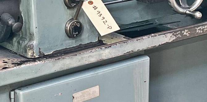
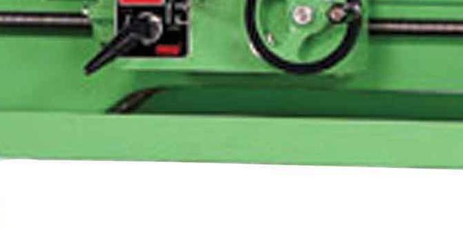
Definition and function of metal lathes. Common components of a metal lathe.Metal lathes are machines that shape metal into objects. They work by spinning the metal and cutting it down to the right size. Think of it as a big metal cookie cutter! The main parts of a metal lathe include the bed, which holds everything steady, and the carriage, which moves the cutting tool. You can also find the headstock that powers the spindle. Together, they help create precise shapes. Here’s a quick look:
| Component | Function |
|---|---|
| Bed | Holds everything in place |
| Carriage | Moves the tool |
| Headstock | Powers the spindle |
With these parts working together, you can create anything from bolts to fancy sculptures. Just remember not to stand too close! Metals can be pretty slippery.
Importance of Proper Wiring in Metal Lathes
Role of wiring in lathe operation. Consequences of improper wiring.Wiring is like the nervous system of a metal lathe. It connects all the parts and helps them work together smoothly. Without proper wiring, things can get messy. You might end up with a machine that has a mind of its own—think “Transformer” but not the cool kind! Miswiring can cause accidents, damage parts, and even lead to injuries. Let’s make sure to keep our wiring neat and tidy, like mom’s kitchen!
| Proper Wiring | Improper Wiring |
|---|---|
| Maintains smooth operation | Causes malfunctions |
| Ensures safety | Increases risk of accidents |
| Boosts machine lifespan | Leads to costly repairs |
Remember, a well-wired lathe is a happy lathe! Proper wiring is key to keeping everything in check. So, let’s get those wires aligned—no one likes a tangled mess!
Components of Tool Post Wiring
Description of essential wiring components. Types of wires and connectors used.Understanding wiring components is important for tool posts. First, you need different types of wires. Copper wires are popular because they conduct electricity well. You also need connectors to link these wires. Some common connectors are terminals, plugs, and sockets. Each has a specific use. Using the right wiring helps ensure safety and good performance in your projects.
- Copper wires: Great for conducting electricity.
- Terminals: Help connect wires securely.
- Plugs: Allow easy connections and disconnections.
- Sockets: Keep connections stable and safe.
What are the essential wiring components for a tool post?
Essential components include copper wires, terminals, plugs, and sockets. Each part plays a role in safely connecting the tool post to the power source.
Step-by-Step Wiring Process
Detailed steps for wiring a tool post metal lathe. Common pitfalls to avoid during wiring.Wiring a tool post metal lathe may sound complex, but it’s like assembling a giant puzzle. First, gather your tools: wires, connectors, and a handy wiring diagram. Start by connecting the power supply to the machine. Make sure the wires fit snugly; loose connections can cause “sparks” – and not the fun kind! Next, link the motor wires correctly to avoid a game of electric tag.
Be careful not to mix up colors! If your wires are red, green, or blue, they all need to stay in their lane. Check your connections multiple times. Remember, double-checking can save you from the dreaded “Oops” moment!
| Step | Action |
|---|---|
| 1 | Gather Tools |
| 2 | Connect Power Supply |
| 3 | Link Motor Wires |
| 4 | Double-check Connections |
If you see sparks, it might be time to panic, but let’s hope it’s just a light show! Following these steps carefully will keep your lathe running smoothly, sparing you mishaps and making your wiring adventure a success.
Troubleshooting Wiring Issues
Identifying common wiring problems. Solutions and fixes for wiring issues.Wiring problems on your tool post metal lathe can feel like solving a puzzle, but without all the fun. Common issues include frayed wires, loose connections, and blown fuses. These problems can cause your lathe to act like it lost its favorite toy! Thankfully, solutions are usually easy. Check for loose wires first—tighten any that look a bit wobbly. If a fuse is blown, replace it. Keeping your wiring neat can also prevent future headaches.
| Problem | Solution |
|---|---|
| Frayed Wires | Wrap with electrical tape or replace |
| Loose Connections | Tighten screws and connectors |
| Blown Fuse | Replace with a new fuse |
Safety Precautions When Wiring
Essential safety practices to follow. Use of protective gear during wiring.Wiring can be tricky, and safety comes first. Always wear protective gear like gloves and goggles. Imagine trying to wire while making a fashion statement—let’s not! Proper tools protect you and your project. If something looks off, don’t just wing it. Check it first! Remember, **better safe than sorry**. Here are some essential practices to keep in mind:
| Safety Practice | Description |
|---|---|
| Wear Gear | Put on goggles and gloves to protect your eyes and hands. |
| Stay Dry | Keep your workspace dry. Water and electricity do not mix! |
| Turn Off Power | Always switch off the power before you start wiring. |
Maintenance Tips for Longevity
Regular checks and maintenance of wiring. Best practices for ensuring optimal function.To keep your metal lathe running well, regular checks are crucial. Look at the wiring often. Damaged wires can cause big problems. Also, make sure to clean dust and grease from parts. This helps everything work better. Here are some best practices for maintenance:
- Check wires for frays or cuts monthly.
- Keep the lathe clean and dry.
- Lubricate moving parts regularly.
- Inspect connections for tightness and cleanliness.
Following these tips can help your lathe last longer and work properly.
How often should I check the wiring?
It’s smart to check the wiring monthly for any signs of wear and tear. Regular checks can prevent bigger issues and keep your lathe safe and efficient.
Conclusion
In conclusion, a tool post metal lathe wiring diagram is essential for setting up your lathe safely and effectively. It shows how to connect the electrical components properly. Understanding this diagram helps you get the most out of your machine. We encourage you to seek out diagrams online or in manuals to practice your skills. Happy lathing!FAQs
What Are The Basic Components Included In A Tool Post Metal Lathe Wiring Diagram?In a tool post metal lathe wiring diagram, we see a few important parts. First, there’s the power source, which is where the electricity comes from. Next, we have the motor, which helps the lathe spin. There are also wires that connect everything, carrying the power. Lastly, we might find switches to turn the machine on and off.
How Do You Interpret The Wiring Diagram For Connecting The Motor And Control Panel Of A Metal Lathe?To read the wiring diagram, look for different symbols. Each symbol shows a part of the lathe, like the motor or control panel. Next, find the lines connecting these symbols. These lines represent wires that carry electricity. Follow the lines to see how everything connects together. This helps you understand how to set up the lathe safely.
What Safety Precautions Should Be Taken When Wiring A Tool Post Metal Lathe?When wiring a tool post metal lathe, make sure to turn off the power first. Always use insulated tools to avoid electric shocks. Keep your hands dry and wear gloves if needed. It’s important to read the machine’s manual for specific safety tips. Lastly, make sure the area is tidy to prevent trips and falls.
Can You Explain The Function Of Each Wire Color In A Typical Metal Lathe Wiring Diagram?Sure! In a typical metal lathe, we often see different wire colors. The black wire usually carries power, helping the lathe run. The white wire is for the return path of electricity, completing the circuit. The green or bare wire is for safety; it’s the ground wire, keeping us safe from electrical shocks. Other colors may control specific parts, but black, white, and green are the most common.
What Are Common Wiring Issues Encountered With Metal Lathes And How Can They Be Identified Using The Wiring Diagram?Common wiring issues with metal lathes include loose wires, burnt connections, and shorts. You can find these problems by looking at the wiring diagram. If a wire looks broken or disconnected, it might cause trouble. A burnt connection may show black marks. You can also check if wires are touching where they shouldn’t, which could cause a short circuit.
{“@context”:”https://schema.org”,”@type”: “FAQPage”,”mainEntity”:[{“@type”: “Question”,”name”: “What Are The Basic Components Included In A Tool Post Metal Lathe Wiring Diagram? “,”acceptedAnswer”: {“@type”: “Answer”,”text”: “In a tool post metal lathe wiring diagram, we see a few important parts. First, there’s the power source, which is where the electricity comes from. Next, we have the motor, which helps the lathe spin. There are also wires that connect everything, carrying the power. Lastly, we might find switches to turn the machine on and off.”}},{“@type”: “Question”,”name”: “How Do You Interpret The Wiring Diagram For Connecting The Motor And Control Panel Of A Metal Lathe? “,”acceptedAnswer”: {“@type”: “Answer”,”text”: “To read the wiring diagram, look for different symbols. Each symbol shows a part of the lathe, like the motor or control panel. Next, find the lines connecting these symbols. These lines represent wires that carry electricity. Follow the lines to see how everything connects together. This helps you understand how to set up the lathe safely.”}},{“@type”: “Question”,”name”: “What Safety Precautions Should Be Taken When Wiring A Tool Post Metal Lathe? “,”acceptedAnswer”: {“@type”: “Answer”,”text”: “When wiring a tool post metal lathe, make sure to turn off the power first. Always use insulated tools to avoid electric shocks. Keep your hands dry and wear gloves if needed. It’s important to read the machine’s manual for specific safety tips. Lastly, make sure the area is tidy to prevent trips and falls.”}},{“@type”: “Question”,”name”: “Can You Explain The Function Of Each Wire Color In A Typical Metal Lathe Wiring Diagram? “,”acceptedAnswer”: {“@type”: “Answer”,”text”: “Sure! In a typical metal lathe, we often see different wire colors. The black wire usually carries power, helping the lathe run. The white wire is for the return path of electricity, completing the circuit. The green or bare wire is for safety; it’s the ground wire, keeping us safe from electrical shocks. Other colors may control specific parts, but black, white, and green are the most common. “}},{“@type”: “Question”,”name”: “What Are Common Wiring Issues Encountered With Metal Lathes And How Can They Be Identified Using The Wiring Diagram? “,”acceptedAnswer”: {“@type”: “Answer”,”text”: “Common wiring issues with metal lathes include loose wires, burnt connections, and shorts. You can find these problems by looking at the wiring diagram. If a wire looks broken or disconnected, it might cause trouble. A burnt connection may show black marks. You can also check if wires are touching where they shouldn’t, which could cause a short circuit.”}}]}