Summary: Control carbide end mill chatter and deflection with a 3/16 inch tool by using stub length, proper speeds, feeds, and rigid setups. This guide ensures precise cuts in tough materials like hardened steel, minimizing unwanted movement for clean, accurate results.
Hey everyone, Daniel Bates here from Lathe Hub! Ever tried milling something tough, only to see your 3/16 inch carbide end mill dancing around like it’s got a mind of its own? It’s a common frustration, and it’s called deflection. This unwanted bending can ruin your workpiece and even damage your tools. But don’t worry! With a few simple strategies and the right approach, we can get that little 3/16 inch end mill cutting straight and true, even in stubborn materials like hardened steel. Let’s dive into how we can master deflection control and achieve those clean, precise cuts you’re after.
Mastering Your 3/16 Inch Carbide End Mill: Deflection Control for Precision Machining
When you’re working with metal, especially harder alloys. Nothing is more frustrating than seeing your end mill flex and vibrate when it should be cutting cleanly. This phenomenon is called deflection, and it’s a common challenge for anyone using smaller diameter end mills, like the popular 3/16 inch carbide variety. Whether you’re a seasoned machinist or just starting out with your milling machine, understanding how to combat deflection is key to achieving accurate parts, a smooth surface finish, and extending the life of your cutting tools.
A 3/16 inch carbide end mill is a fantastic tool for detailed work, engraving, and creating intricate features. However, its small size means it’s more susceptible to bending under cutting forces compared to larger tools. This bending, or deflection, can lead to:
- Oversized or undersized features
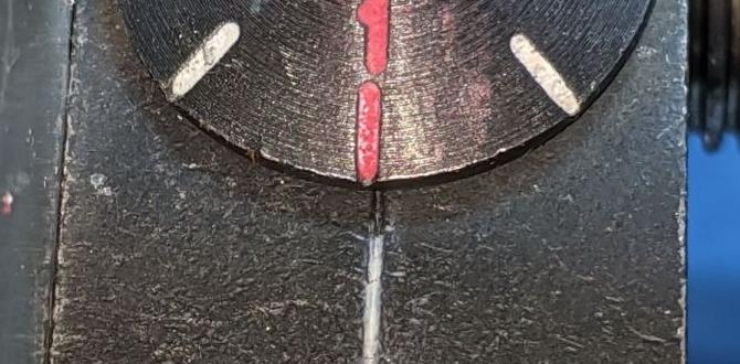
- Poor surface finish with chatter marks
- Increased tool wear or breakage
- Workpiece inaccuracies
- Frustration and wasted material!
The good news is that with the right knowledge and techniques, you can significantly minimize this deflection. This guide will walk you through proven methods for controlling your 3/16 inch carbide end mill, ensuring it performs precisely as you intend, even when tackling challenging metals like hardened steel (HRC 60 and above).
We’ll cover everything from selecting the right type of end mill to setting up your machine and optimizing your cutting parameters. You’ll learn how to make smarter choices that lead to more successful milling projects. Let’s get your workspace set up for success!
Why Does Deflection Happen with Small End Mills?
Imagine trying to push a thin spaghetti noodle through a block of wood. It’s going to bend, right? The same principle applies to your 3/16 inch end mill. Several factors contribute to this “bending” or deflection:
- Cutting Forces: As the cutting edges of the end mill bite into the material, they generate significant force. This force pushes sideways on the tool.
- Tool Length: The longer the tool extends from its holder, the more leverage these cutting forces have. Think of a long lever compared to a short one – the longer one is easier to bend.
- Tool Diameter: A smaller diameter tool inherently has less rigidity than a larger one. It’s simply less “stiff.”
- Material Hardness: Harder materials require more force to cut, directly increasing the forces that cause deflection.
- Machine Rigidity: If your milling machine, vise, or even the workpiece isn’t held very securely, unwanted movement amplifies deflection.
- Cutting Parameters: Incorrect speeds, feeds, and depth of cut can exacerbate cutting forces and lead to chatter and deflection.
Understanding these root causes is the first step to conquering deflection. We can’t change the laws of physics, but we can work smart to minimize their impact.
Choosing the Right 3/16 Inch Carbide End Mill: Your First Line of Defense
Not all 3/16 inch end mills are created equal when it comes to resisting deflection. Making a wise selection before you even turn on the machine is critical.
Stub Length: The Game Changer
For minimizing deflection, especially in harder materials or when you need maximum accuracy, a stub length end mill is your absolute best friend. What does “stub length” mean?
A standard end mill has a certain flute length (the part with the cutting edges) and a total length. A stub length end mill will have a significantly shorter flute length relative to its diameter compared to a standard or “long reach” end mill. Essentially, the shank (the part that holds the tool) is much longer, meaning the cutting edges are closer to the tool holder and the spindle. This drastically reduces the unsupported length of the tool.
For a 3/16 inch diameter end mill, a stub length might have only 1/2 inch or 5/8 inch of flute length, whereas a standard one might have 3/4 inch or even 1 inch. This reduction in overhang is crucial for rigidity.
Number of Flutes: More Isn’t Always Better for Tough Materials
End mills typically come with 2, 3, or 4 flutes. For general milling, 4 flutes are common. However, when cutting tougher materials and aiming to control deflection, a 2-flute or 3-flute end mill is often preferred:
- 2-Flute: Offers excellent chip evacuation, which is vital for preventing chip recutting and overheating, especially in aluminum. They can also be more resistant to chatter in some applications.
- 3-Flute: Provides a good balance between chip clearance and tool rigidity. They can handle slightly higher feed rates than 2-flute mills in some materials.
- 4-Flute (General Purpose): While great for general machining and finishing in softer materials, the tighter chip pockets can sometimes lead to chip packing and increased cutting forces in tougher metals, potentially worsening deflection.
For hardened steel, a 2-flute or 3-flute end mill is generally the way to go.
Coating and Material Type
You’re already looking at carbide, which is essential for its hardness and ability to handle higher cutting temperatures, especially in hardened steel. For extra performance and wear resistance in tough materials, consider end mills with specialized coatings:
- TiAlN (Titanium Aluminum Nitride): Excellent for high-temperature applications and machining steels, including hardened steels, stainless steels, and titanium. It offers superior hardness and thermal resistance.
- AlTiN (Aluminum Titanium Nitride): Similar to TiAlN, offering excellent performance in high-speed machining of steels.
- ZrN (Zirconium Nitride): A good general-purpose coating that provides improved lubricity and wear resistance.
For your 3/16 inch stub length end mill used on hardened steel, a TiAlN or AlTiN coating would be highly beneficial.
Dedicated “High Feed” or “Slotting” End Mills
Some specialized end mills are designed for specific tasks. While a general-purpose stub length end mill is usually sufficient, be aware that high-performance end mills designed for high-feed milling or slotting might offer even better deflection resistance due to their geometry and intended use.
Optimizing Your Setup for Minimal Deflection
Even with the perfect end mill, a poor setup will lead to deflection. Your goal here is maximum rigidity from the machine spindle all the way to the workpiece.
Rigid Tool Holding is Paramount
This is non-negotiable. A flimsy connection between your end mill and the machine spindle is a direct invitation for deflection.
- Collet Chucks: These offer the best runout and gripping force compared to basic drill chucks. A good quality collet chuck (like a CAT, BT, or HSK system for larger machines, or a precise drill chuck with ER collets for smaller machines) ensures the end mill is held perfectly centered and securely.
- ER Collets: If you’re using an ER collet chuck system, ensure you’re using the correct size collet. Using a 3/16 inch end mill in a collet that’s slightly too large or too small will not provide optimal grip and can introduce runout.
- Avoid Drill Chucks if Possible: While a three-jaw drill chuck can hold an end mill, it’s generally not precise enough for demanding milling operations and is far less rigid than a proper collet system. If you must use one, ensure it’s a high-quality, precision chuck.
- Short Tool Stickout: As mentioned with stub length end mills, minimize the amount of end mill shank sticking out of the collet or chuck. Hold it as close to the cutting flutes as possible.
Secure Workholding
The workpiece needs to be absolutely still. Any movement of the part under cutting forces will manifest as deflection or chatter.
- Solid Vise: Use a robust milling vise that is securely bolted to your machine table.
- Clamping: For larger or irregularly shaped parts, consider using clamps directly on the machine table. Ensure clamps are positioned to resist the cutting forces effectively. Never rely on just one clamping point if there’s a risk of the workpiece shifting.
- Parallel Stock: If using a vise, ensure your jaws are gripping on solid, flat surfaces of the workpiece. Use parallels under the workpiece in the vise if needed to achieve proper grip height and prevent the vise jaws from tilting.
- Avoid Fixturing Gaps: Make sure there are no unexpected air gaps or loose points in your setup. A small shim here or there can make a big difference in rigidity.
Machine Tool Condition
A worn or loose machine will amplify deflection. Ensure your machine’s ways are lubricated, gibs are properly adjusted, and there’s no excessive play in the spindle bearings or table/axis components.
For more on machine setup and workholding, resources like the National Institute of Standards and Technology (NIST) offer valuable insights into precision machining practices.
Calculating and Setting Speeds and Feeds for Deflection Control
This is where many beginners struggle, but it’s crucial. Incorrect speeds and feeds are major contributors to chatter and deflection. We need to find a balance that allows the carbide to cut efficiently without being overloaded.
Surface Speed (SFM) and Spindle Speed (RPM)
Carbide tools generally perform well at higher spindle speeds. However, for tougher materials and to manage deflection, a slightly conservative approach can sometimes be beneficial. The cutting speed is measured in Surface Feet per Minute (SFM).
The formula to calculate spindle speed (RPM) is:
RPM = <span>(SFM × 3.82) / Diameter</span>
Where:
- RPM = Revolutions Per Minute of the spindle
- SFM = Desired Surface Feet per Minute (recommendations vary by material and tool)
- Diameter = Tool Diameter in inches
- 3.82 is a conversion factor
For 3/16 inch (0.1875 inch) carbide end mills cutting hardened steel (e.g., HRC 60), SFM recommendations can range from 200-400 SFM or even lower, depending on the specific alloy, coating, and your machine’s rigidity.
Let’s take a conservative starting point for hardened steel, say 250 SFM:
RPM = (250 × 3.82) / 0.1875 = 955 / 0.1875 ≈ 5093 RPM
If your machine can’t reach this speed or you experience chatter, you might need to try a slightly lower SFM or adjust feed rates.
Chip Load (CL) and Feed Rate (IPM)
Chip load refers to the thickness of the material each cutting edge removes per revolution. This is critical for preventing tool damage and chatter.
The formula for Feed Rate (IPM – Inches Per Minute) is:
IPM = <span>Chip Load × Number of Flutes × RPM</span>
Where:
- IPM = Inches Per Minute
- Chip Load (CL) = The desired chip thickness per tooth (inches/tooth)
- Number of Flutes = The number of cutting edges on your end mill
- RPM = Spindle Speed calculated above
For a 3/16 inch, 2-flute carbide end mill in hardened steel, a conservative chip load might be as low as 0.001 to 0.002 inches per tooth.
Let’s use a chip load of 0.0015 inches/tooth with our calculated RPM of 5093:
IPM = 0.0015 × 2 × 5093 = 15.28 IPM
This is a very light feed rate. When dealing with deflection in hard materials, you often need to use a lighter chip load but maintain a decent RPM to keep the chip moving. It’s a balance!
Feed Per Tooth vs. Chip Load
Sometimes you’ll see “feed per tooth” (FPT) used interchangeably with chip load. They mean the same thing. Manufacturers often provide recommended chip loads for their tools and specific materials.
Why Lighter Chip Loads Help Deflection
A lighter chip load means each cutting edge is taking a thinner slice of material. This reduces the overall cutting force acting on the end mill, thus reducing deflection. It’s like slicing bread very thinly versus trying to hack off a thick chunk.
Advanced Deflection Control Strategies
Beyond tool choice and basic setup, several advanced techniques can significantly improve your results.
Depth of Cut (DOC) – The Most Important Parameter!
This is arguably the most impactful setting for deflection control, especially with smaller tools. The depth of cut is how deep the end mill cuts into the material vertically.
- Shallow DOC: Using a very small depth of cut (e.g., 0.010″ to 0.020″ for a 3/16″ end mill in hardened steel) is your primary weapon against deflection. This dramatically reduces the cutting forces acting on the tool.
- Radial Depth of Cut: This refers to how far the tool engages the material sideways. For full slotting, it’s typically 100% of the tool’s diameter. For contouring or pocketing where you’re not cutting a full slot, you can engage less than the tool’s diameter. Less radial engagement means less cutting force.
- High-Feed Milling (Trochoidal Milling): This technique involves taking very shallow axial depths of cut and large radial depths of cut (often >50% of the tool diameter) using small stepovers. The tool moves in a circular path, engaging and disengaging the material continuously. This strategy is excellent for slotting and pocketing in hard materials and can be very effective at managing chip load and deflection, though it requires specific CAM strategies. For manual machining, it translates to making many shallow passes.
Stepover for Pocketing and Contouring
When you’re milling a pocket or contouring a shape, the “stepover” is the lateral distance the tool moves between passes. For deflection control:
- Smaller Stepover: A smaller stepover means the tool is engaged in thinner cuts sideways, reducing radial cutting forces. This is particularly important when finishing passes are needed.
- Optimum Stepover: While small is good for deflection, too small a stepover can lead to inefficient machining and a “scallop” effect on the surface if not managed. Manufacturers often provide recommendations for optimal stepovers based on tool diameter and material.
Climb Milling vs. Conventional Milling
The direction the tool rotates relative to the feed direction matters:
- Climb Milling: The tool rotates in the same direction as the feed. This makes the chip start thin and get thicker as it’s cut. It generally results in a better surface finish and can reduce forces, particularly when starting a cut. Many modern CNC operations default to climb milling.
- Conventional Milling: The tool rotates against the direction of the feed. The chip starts thick and gets thinner. This can sometimes lead to more chatter and increased tool wear, but can be more predictable in some older machines or when dealing with very gummy materials.
For minimizing deflection in hard materials, climb milling is often preferred as it tends to push the workpiece/cutter away (rather than pull) when starting the cut, potentially reducing initial shock. However, always ensure your machine has zero backlash for effective climb milling