Have you ever wondered how machines create perfect shapes from raw metal? If you love tinkering and building things, you might find a gearhead metal lathe fascinating. This machine cuts and shapes metal with great precision. Imagine how much fun it would be to design your own metal projects.
With CAD design, you can turn your creative ideas into reality. CAD stands for Computer-Aided Design. It helps you visualize and plan your work before you even touch a lathe. This way, you can make sure everything fits perfectly. Isn’t that cool?
The best part is that anyone can learn to use CAD software. You just need some practice. Once you know how to use it, the possibilities are endless. From making gears to crafting art pieces, a gearhead metal lathe can help bring your designs to life.
So, grab your imagination and let’s dive deeper into the world of gearhead metal lathes and CAD design. You might discover a new hobby or even a career you hadn’t thought of before!
Gearhead Metal Lathe Cad Design: A Comprehensive Guide
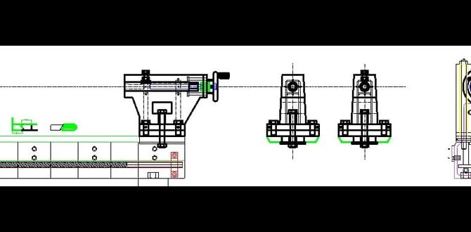
Gearhead Metal Lathe CAD Design
Gearhead metal lathe CAD design lets you create precise machine parts. This design process helps engineers visualize and plan their work before they start. Imagine building a custom part for a project! You can design everything from tools to car parts. Did you know most modern machines use CAD software? With CAD, you can easily modify your designs. This flexibility saves time and materials, making your projects efficient and fun!Understanding Gearhead Metal Lathes
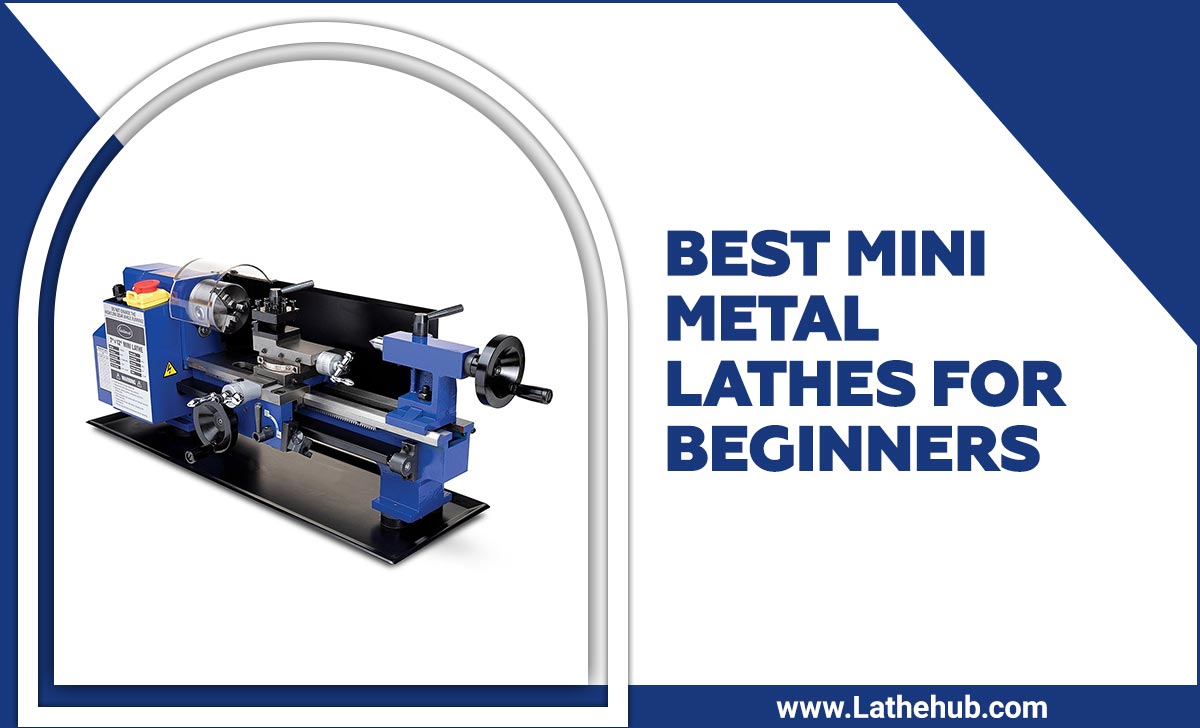
Definition and function of gearhead metal lathes. Key components and their roles in machining processes.A gearhead metal lathe is a powerful machine tool used in workshops. It helps shape metal into precise parts. This lathe has key components that work together during a machining process.
- Headstock: Contains the motor and drives the lathe’s spindle.
- Tailstock: Supports the workpiece and holds tools for drilling.
- Carriage: Moves the cutting tool across the workpiece.
- Bed: Supports the entire machine and keeps it stable.
These parts help create smooth, finished products from metal. Using a gearhead metal lathe can make many items, from toys to car parts.
What is a gearhead metal lathe used for?
A gearhead metal lathe is used for shaping and cutting metal. It creates parts for machines or tools, making it essential in many industries.
Benefits of Using CAD for Metal Lathe Design
Enhancements in precision and accuracy. Streamlined design and manufacturing processes.Using CAD for metal lathe design offers many benefits. It enhances precision and accuracy through detailed software tools. This means parts fit better and work well. Additionally, CAD streamlines design and manufacturing processes. Designers can easily modify their work, leading to faster production times. This saves money and resources.
How does CAD improve metal lathe design?
CAD improves metal lathe design by increasing accuracy and speeding up the process. Faster design means less time waiting. More precise parts reduce errors in the final product.
- Increased precision leads to better results.
- Faster design saves time and money.
Basic Principles of CAD Design for Gearhead Lathes
Key concepts in engineering drawing and design. Importance of tolerances and fits in lathe components.Creating a gearhead lathe design involves some basic rules. First, engineers use engineering drawings to map out the details. These drawings act like treasure maps for builders. Next, tolerances and fits are key! They ensure parts fit together without going on a wild adventure! Too loose? They’ll wobble like they’re dancing. Too tight? They might just burst!
| Term | Description |
|---|---|
| Tolerances | The allowable variation in a part’s dimensions. |
| Fits | The relationship between two parts and how they connect. |
Understanding this helps prevent mishaps and unhappy lathe hugs. Good design means happy gears! And nobody wants cranky machinery, right?
Step-by-Step Guide to Designing a Gearhead Metal Lathe in CAD
Initial concept and sketching techniques. Modeling components such as headstock, tailstock, and carriage.Start by imagining your gearhead metal lathe. Draw a simple sketch. Focus on the main parts, like the headstock and tailstock. Use paper or a digital tool. Think about how these parts fit together. Next, model each component using CAD software. Make sure the design is clear and easy to understand. Pay attention to details. A good design starts with a solid idea and ends with precise features.
How do I begin designing a metal lathe?
Begin with sketches to visualize each part clearly. Think about the size and shape that fit your project.
Key components to focus on:
- Headstock
- Tailstock
- Carriage
Common Challenges in Gearhead Metal Lathe CAD Design
Potential design pitfalls and how to avoid them. Solutions for managing complex geometry and assembly.Designing a gearhead metal lathe in CAD can be tricky. One pitfall is ignoring tiny details. They may seem small, but they can ruin your whole design like a shoe at a dance party! Complex geometry can also be tough. To tackle this, break shapes into smaller parts. It’s like cutting a pizza before sharing! For assembly, always check if parts fit together. Remember, even machines need friends!
| Challenge | Solution |
|---|---|
| Ignoring small details | Focus on details and double-check! |
| Complex geometry | Break designs into manageable segments. |
| Poor assembly fit | Verify all parts before finalizing. |
Testing and Validating Your CAD Design
Importance of simulation and testing in the design phase. Methods for ensuring design functionality and manufacturability.Testing your CAD design is essential. It helps you see if your idea works well. Using simulation can show how the design behaves under different conditions. This step is crucial to catch problems early. Here are some methods to ensure functionality and manufacturability:
- Run simulations for stress and strain.
- Check if parts fit together correctly.
- Look for manufacturing issues, like difficult shapes.
Remember, the earlier you find problems, the cheaper they are to fix!
Why is simulation important in CAD design?
Simulation helps identify issues early, saving time and money later. It also shows how parts will function together.
Real-world Applications and Case Studies
Examples of successful gearhead lathe designs in industries. Lessons learned from practical implementations and modifications.Many companies use gearhead lathes to create amazing products. For example, in the automotive industry, these tools help shape car parts. This speeds up production and makes parts fit better. One important lesson learned from using these lathes is that even a tiny adjustment can lead to big improvements. In fact, some users found that small changes in speed led to smoother operations. Just like how a sprinkle of salt can make cookies taste better!
| Industry | Application | Key Lesson |
|---|---|---|
| Automotive | Shaping car parts | Small speed changes matter |
| Aerospace | Creating precision components | Regular maintenance is crucial |
| Manufacturing | Producing tools and fixtures | Testing before full production |
Future Trends in CAD Design for Metal Lathes
Emerging technologies and innovations in CAD for machining. Predictions for the impact of automation and AI in lathe design.Exciting changes are on the horizon for CAD design in metal machining! Imagine using 3D printing alongside your metal lathe. This tech can make parts faster and cheaper. You might even see robots zipping around the workshop. They will work as helpful assistants, taking on boring tasks, so you can focus on being creative. Automation and AI are not just buzzwords; they will transform how we design and make things. The future looks bright in the world of gears and lathes!
| Trend | Description |
|---|---|
| 3D Printing | Makes parts quickly and reduces costs. |
| Automation | Robots help with repetitive tasks. |
| AI Integration | Improves design efficiency and creativity. |
Conclusion
In summary, a gearhead metal lathe is a powerful tool for precision work. Using CAD design, you can plan your projects efficiently. This helps you visualize your ideas and improve your skills. We encourage you to explore more about CAD programs and try creating your designs. With practice, you’ll become a confident gearhead!FAQs
Here Are Five Related Questions On The Topic Of Gearhead Metal Lathe Cad Design:Sure! Gearhead metal lathes are machines that help us make round parts out of metal. CAD stands for Computer-Aided Design, which means we use a computer to plan our designs. When we use CAD for lathes, we can see how our parts will look before making them. This helps us fix any mistakes quickly. Designing with CAD makes it easier to create cool projects!
Sure! Please ask your question, and I will do my best to help you.
What Are The Key Design Considerations When Creating A Cad Model For A Gearhead Metal Lathe?When creating a CAD model for a gearhead metal lathe, you should think about size and shape first. Make sure all parts fit together well. It’s also important to consider how strong the materials are. You should plan for where the motor will go and how it will turn. Lastly, check that everything is easy to reach for using the machine.
How Can Cad Software Be Utilized To Optimize The Performance And Efficiency Of A Gearhead Metal Lathe?You can use CAD software to design gears for a metal lathe. This helps make sure the parts fit perfectly. You can also test how fast they will move. By changing the designs easily, you can find the best shapes. This makes the lathe work better and last longer.
What Types Of Materials Are Typically Used In The Construction Of Gearhead Components In A Lathe Design, And How Can Cad Help In Selecting These Materials?The gearhead in a lathe is usually made of strong metals like steel or aluminum. We use these metals because they can handle heavy tasks. CAD, which stands for Computer-Aided Design, helps us pick the best materials. It lets us see how different materials will work before we make anything. Using CAD makes our choices smarter and faster!
How Do You Incorporate Tolerances And Fits Into Your Cad Design For A Gearhead Metal Lathe To Ensure Proper Assembly And Function?To make sure parts fit together well in our gearhead metal lathe, we need to set tolerances. Tolerances are small measurements that tell us how much space we can allow between parts. In our CAD design, we can use tools to show these spaces. We also check the parts to see if they fit correctly when we build the lathe. This way, everything works smoothly and safely!
What Are The Advantages Of Using Parametric Design In Cad For Modeling The Gearhead Assembly Of A Metal Lathe?Using parametric design in CAD, or Computer-Aided Design, helps us make changes easily. If you want to adjust the size of a gear, you just change one number, and everything else updates automatically. This saves time and makes it easier to fix mistakes. We can also see how parts fit together better, which helps us build stronger machines. Overall, it makes our work faster and more fun!
{“@context”:”https://schema.org”,”@type”: “FAQPage”,”mainEntity”:[{“@type”: “Question”,”name”: “Here Are Five Related Questions On The Topic Of Gearhead Metal Lathe Cad Design:”,”acceptedAnswer”: {“@type”: “Answer”,”text”: “Sure! Gearhead metal lathes are machines that help us make round parts out of metal. CAD stands for Computer-Aided Design, which means we use a computer to plan our designs. When we use CAD for lathes, we can see how our parts will look before making them. This helps us fix any mistakes quickly. Designing with CAD makes it easier to create cool projects!”}},{“@type”: “Question”,”name”: “”,”acceptedAnswer”: {“@type”: “Answer”,”text”: “Sure! Please ask your question, and I will do my best to help you.”}},{“@type”: “Question”,”name”: “What Are The Key Design Considerations When Creating A Cad Model For A Gearhead Metal Lathe?”,”acceptedAnswer”: {“@type”: “Answer”,”text”: “When creating a CAD model for a gearhead metal lathe, you should think about size and shape first. Make sure all parts fit together well. It’s also important to consider how strong the materials are. You should plan for where the motor will go and how it will turn. Lastly, check that everything is easy to reach for using the machine.”}},{“@type”: “Question”,”name”: “How Can Cad Software Be Utilized To Optimize The Performance And Efficiency Of A Gearhead Metal Lathe?”,”acceptedAnswer”: {“@type”: “Answer”,”text”: “You can use CAD software to design gears for a metal lathe. This helps make sure the parts fit perfectly. You can also test how fast they will move. By changing the designs easily, you can find the best shapes. This makes the lathe work better and last longer.”}},{“@type”: “Question”,”name”: “What Types Of Materials Are Typically Used In The Construction Of Gearhead Components In A Lathe Design, And How Can Cad Help In Selecting These Materials?”,”acceptedAnswer”: {“@type”: “Answer”,”text”: “The gearhead in a lathe is usually made of strong metals like steel or aluminum. We use these metals because they can handle heavy tasks. CAD, which stands for Computer-Aided Design, helps us pick the best materials. It lets us see how different materials will work before we make anything. Using CAD makes our choices smarter and faster!”}},{“@type”: “Question”,”name”: “How Do You Incorporate Tolerances And Fits Into Your Cad Design For A Gearhead Metal Lathe To Ensure Proper Assembly And Function?”,”acceptedAnswer”: {“@type”: “Answer”,”text”: “To make sure parts fit together well in our gearhead metal lathe, we need to set tolerances. Tolerances are small measurements that tell us how much space we can allow between parts. In our CAD design, we can use tools to show these spaces. We also check the parts to see if they fit correctly when we build the lathe. This way, everything works smoothly and safely!”}},{“@type”: “Question”,”name”: “What Are The Advantages Of Using Parametric Design In Cad For Modeling The Gearhead Assembly Of A Metal Lathe?”,”acceptedAnswer”: {“@type”: “Answer”,”text”: “Using parametric design in CAD, or Computer-Aided Design, helps us make changes easily. If you want to adjust the size of a gear, you just change one number, and everything else updates automatically. This saves time and makes it easier to fix mistakes. We can also see how parts fit together better, which helps us build stronger machines. Overall, it makes our work faster and more fun!”}}]}

