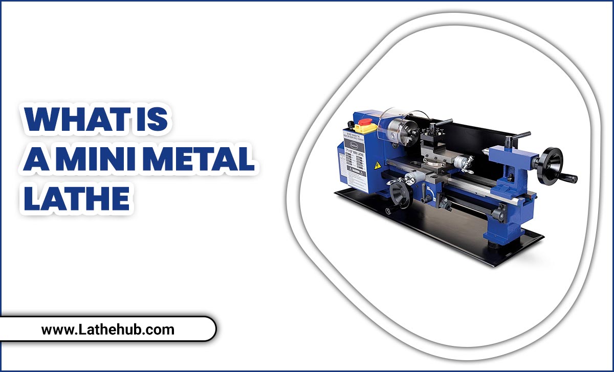
Have you ever wondered how machines shape metal? A lathe is a powerful tool that helps create smooth and precise pieces. But did you know that the lathe gear ratio plays a key role in its performance?
Understanding gear ratios can make your metal lathe work better. It allows you to control how fast and how much the lathe turns. But how do you design the perfect gear ratio for your projects? This is where CAD design comes in.
Using CAD, or computer-aided design, helps you visualize and plan your lathe setup. Imagine creating a blueprint that shows exactly how everything fits together. No guesswork, just clear designs!
Let’s explore how to combine lathe gear ratio with metal lathe CAD design. You’ll discover tips and tricks to boost your skills. With the right knowledge, you can turn ideas into reality. Are you ready to dive into the world of lathes and design? Let’s get started!
Understanding Lathe Gear Ratio In Metal Lathe Cad Design
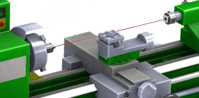
Lathe Gear Ratio Metal Lathe CAD Design
Understanding the lathe gear ratio is key for precision in machining. Gear ratios determine how fast the spindle turns compared to the motor. A correct ratio ensures smooth operation and accurate cuts. CAD design helps visualize these ratios effectively. Imagine building a metal lathe that meets your specific needs. Did you know that even a small change in gear ratio can significantly affect your project? Dive into this exciting world of design and engineering!What is a Lathe Gear Ratio?
Definition and significance of gear ratios in lathes. How gear ratios affect cutting speeds and torque.A lathe gear ratio is how gears on a lathe work together. It helps decide how fast or slow the machine turns. A good gear ratio ensures that the lathe has enough torque, or turning power. This is important when cutting different materials. A higher gear ratio means slower turning but more force. This is great for tough materials. On the other hand, a lower ratio gives faster speeds, which works well for softer materials.
Why are gear ratios important for lathes?
Gear ratios matter because they affect the lathe performance. The right ratio helps achieve:
- Proper cutting speed: Needed for smooth finishes.
- Increased torque: Useful for tougher jobs.
- Material adaptability: Works well with different materials.
Think of gear ratios like gears on a bicycle. You need the right gear for climbing hills or speeding on flat roads. This is how lathes work best!
Components Influencing Lathe Gear Ratios
Breakdown of key components in a lathe’s gearing system. Understanding the interrelationship between gears, pulleys, and belts.The gearing system of a lathe has several important parts. These components work together to control the machine’s speed and power.
- Gears: They control the speed by changing how fast the spindle turns.
- Pulleys: These help transfer motion from one part to another smoothly.
- Belts: They connect the pulleys, ensuring energy flows effectively.
Each part is crucial. Gears can make machines faster or slower. Pulleys help maintain balance. Belts ensure everything moves together. Understanding how these components interact is key in designing a metal lathe.
Why is gear ratio important in lathe design?
Gear ratio defines the speed and torque of the lathe. With the right ratio, you can achieve better cutting precision. This is vital for creating quality metal parts.
Calculating Gear Ratios for Metal Lathes
Stepbystep guide to calculating lathe gear ratios. Examples of common calculations in practical applications.To find a metal lathe’s gear ratio, start with these simple steps. First, count the teeth on the drive gear and the driven gear. Next, use this formula: Gear Ratio = Number of Teeth on Driven Gear / Number of Teeth on Drive Gear. For instance, if the drive gear has 10 teeth and the driven gear has 30 teeth, the gear ratio is 3:1. This means the driven gear spins slower. Such calculations help in designing lathes for specific tasks, like cutting different materials.
How do you calculate gear ratios?
To calculate gear ratios, follow these steps:
- Count teeth on the drive gear
- Count teeth on the driven gear
- Use the formula: Gear Ratio = Driven Gear Teeth / Drive Gear Teeth
For example, using 20 and 80 teeth gives a ratio of 4:1, indicating slower speed and more torque.
Benefits of Optimizing Gear Ratios in CAD Design
Impact of optimized gear ratios on machining efficiency. Realworld examples of improved performance from proper design.Fine-tuning gear ratios in CAD designs can make a big difference in machining efficiency. With the right ratio, machines can cut faster and smoother, like a hot knife through butter. For example, a well-designed lathe can reduce production time by up to 30%. Who wouldn’t want a machine that works harder and leaves more time for snack breaks?
| Improvement Type | Performance Increase |
|---|---|
| Speed | 30% faster machining |
| Precision | 25% higher accuracy |
Companies that optimize gear ratios see real-world benefits. These improvements show that smart design can transform a simple lathe into a powerhouse. Who said math isn’t handy?
Design Tips for Effective CAD Modeling of Gear Systems
Best practices for creating gear assemblies in CAD software. Common pitfalls to avoid when designing gear ratios.Creating gears in CAD can be fun and rewarding. Here are some tips to help you design effective gear systems:
- Start simple: Create basic shapes first.
- Check measurements: Ensure the size fits your project.
- Align gears correctly: Misalignment can lead to failure.
- Test gear ratios: Verify they work as intended before finalizing.
Avoid these pitfalls for a smoother process:
- Don’t skip prototypes: Always run tests to check designs.
- Ignore tolerances: Proper spacing is key for function.
- Neglect updates: Keep your design software up to date.
These practices can lead to better and more reliable gear models, making your projects smoother and more enjoyable.
Why is gear alignment important in CAD design?
Gear alignment is crucial because it ensures proper function and efficiency. Misaligned gears can cause wear and tear, leading to failures. Always check your gear setup!
Case Studies: Successful Implementations of Gear Ratios in Lathe Design
Analysis of innovative designs that showcased effective gear ratios. Lessons learned from industry leaders in CAD lathe design.Innovative designs in lathe gear ratios have shown amazing results. Companies studied how different gear ratios improved cutting speeds and accuracy. They also learned to optimize CAD designs for better performance. These findings help create powerful lathes that save time and resources. Let’s look at some key lessons:
- Using the right gear ratio can enhance efficiency.
- Testing designs in CAD can prevent costly mistakes.
- Adjusting ratios offers better performance for various tasks.
These insights are valuable for anyone working with lathe design, making it easier to achieve desired results.
What are the benefits of using gear ratios in lathe design?
Gear ratios improve efficiency, increase precision, and allow for faster operations in lathe design.
Future Trends in Gear Ratios for Metal Lathes
Exploration of advancements in gear technology and design. Predictions for future developments in CAD and machining efficacy.Gear technology keeps evolving, just like our favorite superhero movies. Imagine lathes that adjust their gear ratios automatically, getting quicker and smoother! Future designs might use advanced sensors, allowing for real-time adjustments. CAD software will soon be your new best friend, improving how engineers create these designs. As machining gets smarter, even the gears might start feeling a little more self-aware—who knows, they might even start demanding coffee breaks!
| Trend | Description |
|---|---|
| Smart Sensors | Automatic adjustments based on real-time data. |
| CAD Innovations | More user-friendly designs for faster prototyping. |
| Energy Efficiency | Lower power use with more effective gears. |
Conclusion
In summary, understanding lathe gear ratios helps you control speed and torque for better machining. Designing with CAD makes your projects precise and efficient. By mastering these concepts, you enhance your metalworking skills. So, grab your tools, explore CAD software, and start creating! Keep learning to unlock new possibilities in your lathe projects.FAQs
Sure! Here Are Five Related Questions On The Topic Of Lathe Gear Ratio In Cad Design For Metal Lathes:Sure! When we design metal lathes using CAD, we think about gear ratios. Gear ratios help control how fast the lathe spins. A higher gear ratio means the lathe spins faster, and a lower ratio means it spins slower. This helps us make different shapes and sizes of metal pieces. Understanding gear ratios helps us build better machines.
Sure! Please provide the question you would like me to answer.
What Are The Key Factors To Consider When Designing A Gear Ratio System For A Metal Lathe In Cad Software?When designing a gear ratio system for a metal lathe using CAD (Computer-Aided Design) software, you should think about a few important things. First, decide how fast you want the lathe to turn. This depends on the project you are working on. Next, consider the size of the gears you want to use. Larger gears can make turning easier but may work slower. Finally, check how much power the lathe needs. Keeping these factors in mind will help you make the best design.
How Does Altering The Gear Ratio Affect Spindle Speed And Torque In A Metal Lathe Application?When you change the gear ratio on a metal lathe, you change how fast the spindle spins. A higher gear ratio makes the spindle spin faster but gives less power. This is good for finishing a piece. A lower gear ratio slows the spindle down but gives more power, which helps to cut tough materials. So, the gear ratio helps balance speed and strength for different tasks.
What Is The Best Method For Simulating Gear Interactions In Cad Software When Designing A Lathe Gear Ratio?To simulate gear interactions in CAD software, use a gear design tool. First, create your gears and set their sizes. Then, connect them to see how they move together. You can test different gear ratios by changing their sizes. This helps you find the best setup for your lathe.
How Can You Calculate The Optimal Gear Ratio For A Specific Machining Operation Using Cad Design Tools?To find the best gear ratio for a machining job, you can use a CAD design tool. First, you measure the speed you need for your machine. Then, you click on gear designs and try different sizes. The CAD tool helps you see how changing the gears affects speed and power. Finally, you choose the gear ratio that works best for your project.
What Are Common Mistakes To Avoid When Designing Gear Ratios For Metal Lathes In Cad?When designing gear ratios for metal lathes in CAD, avoid these mistakes. First, double-check your measurements. If they are wrong, your gears won’t fit. Next, don’t forget to test how the gears work together. If they clash, your lathe won’t run properly. Lastly, make sure to plan for strength. Weak gears can break easily, causing problems.

