Quick Summary: The TiAlN ball nose end mill with a 35-degree helix angle is a top choice for precise G10 machining. Its specialized coating and geometry excel at handling this tough composite, minimizing chipping and heat for clean, accurate results.
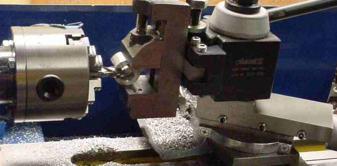
Hey everyone, Daniel Bates here from Lathe Hub! Ever found yourself wrestling with G10, that super-tough fiberglass laminate that’s fantastic for parts but a real pain to machine? You’re not alone! Many of us have faced frustrating chips, tool breakage, and less-than-perfect finishes when trying to get those intricate G10 components just right. It can be a real head-scratcher, especially when precision is key. But don’t worry, there’s a specific tool that can make all the difference. In this guide, I’ll walk you through exactly why a TiAlN ball nose end mill with a 35-degree helix angle is your secret weapon for G10 precision. We’ll cover everything you need to know to get those clean, accurate cuts you’re aiming for, every single time.
Why G10 Demands Special Tools
G10 is a composite material made from layers of fiberglass cloth soaked in epoxy resin. This combination makes it incredibly strong, lightweight, and resistant to heat and moisture. It’s a dream for functional parts, but a nightmare for standard cutting tools. The fiberglass fibers act like tiny abrasives, while the epoxy resin can gum up and melt, creating excessive heat. These factors combined can lead to:
- Rapid Tool Wear: Your average end mill will dull quickly.
- Chipping and Delamination: The layers of G10 can tear instead of cutting cleanly.
- Melting and Guming: The epoxy can melt, sticking to your tool and creating a mess.
- Poor Surface Finish: You might end up with rough, fuzzy edges.
- Tool Breakage: When tools struggle, they tend to snap, especially in harder materials.
This is where specialized tooling comes into play. We need something that can cut through those tough fibers without shattering, resist the heat generated, and provide a good surface finish. For complex G10 parts, especially those with curved surfaces or detailed pockets, a ball nose end mill is often the perfect shape. But not just any ball nose end mill will do.
The TiAlN Ball Nose End Mill 35 Degree: A Closer Look
Let’s break down why this specific tool is so effective for G10:
1. TiAlN Coating: The Heat Shield
TiAlN stands for Titanium Aluminum Nitride. This is a high-performance coating applied to the cutting tool. Here’s why it’s a game-changer for G10:
- Excellent Heat Resistance: G10 generates a lot of friction and heat when machined. TiAlN can withstand much higher temperatures than uncoated or even TiN (Titanium Nitride) coated tools. This means the cutting edge stays sharper for longer, even under high heat.
- Increased Hardness: The coating adds an extra layer of hardness, helping the tool resist the abrasive nature of the fiberglass and epoxy in G10.
- Reduced Friction: TiAlN helps reduce the friction between the tool and the workpiece, which further minimizes heat buildup and prevents material from welding to the cutter.
- Longer Tool Life: Because it resists heat and wear so well, a TiAlN coated tool will last significantly longer when cutting G10 compared to other options.
Think of it like a heat-resistant shield for your end mill, allowing it to slice through tough material without melting or becoming dull too quickly.
2. Ball Nose Geometry: For Smooth Curves and Contours
A ball nose end mill has a rounded tip, resembling a ball. This shape is crucial for certain G10 applications:
- 3D Contouring: Essential for creating curved surfaces, fillets, and complex 3D shapes without leaving sharp corners or tool marks that would require extensive finishing.
- Pocketing: While not ideal for flat-bottomed pockets, it’s excellent for creating radiused or contoured internal features.
- Engraving and Detail Work: The rounded tip allows for fine detail and precise engraving on the G10 surface.
- Reduced Stress Concentration: Unlike a square end mill, the rounded tip distributes cutting forces more evenly, reducing the risk of chipping at the corners of the cut.
Imagine trying to sculpt a smooth curve with a square chisel versus a rounded gouge. The ball nose end mill is the gouge – perfect for shaping organic forms and intricate details.
3. The 35-Degree Helix Angle: The Sweet Spot for Composites
The helix angle refers to the angle of the flutes (the spiral cutting edges) on the end mill. For G10, a 35-degree helix angle often hits a sweet spot. Here’s why:
- Chip Evacuation: A steeper helix angle (like 45 degrees or more) can sometimes lead to more chip recutting in composites, causing heat and poor finishes. A shallower angle (like 30 degrees or less) might not provide enough shear for clean cutting. The 35-degree angle strikes a balance, allowing for effective chip evacuation without excessive force.
- Smooth Cutting Action: This angle often provides a good shearing action against the G10, helping to cut through the material cleanly rather than just grinding it. This reduces the tendency for chipping and delamination.
- Reduced Radial Force: A moderate helix angle can help reduce the sideways (radial) forces applied to the workpiece, which is beneficial when machining thinner G10 sections or detailed features.
- Optimized for Composites: Many tool manufacturers develop helix angles specifically for advanced materials. 35 degrees has proven effective for many fiberglass and carbon fiber reinforced plastics, including G10.
This specific helix angle is designed to work harmoniously with the TiAlN coating and the ball nose geometry to provide the best cutting performance in challenging materials like G10.
Understanding the Basics of End Mills
Before we dive deeper into how to use it, let’s quickly review what makes an end mill tick. An end mill is a type of milling cutter used to create flat-bottomed slots, pockets, and profiles. They can cut in multiple directions but are primarily used for side milling.
Key End Mill Features:
- Flutes: The spiral grooves along the cutting edge. More flutes generally mean a smoother finish but can be less effective at chip evacuation. Fewer flutes are better for softer materials or higher feed rates. For composites like G10, typically 2-flute to 4-flute are used.
- Helix Angle: As discussed, this is the spiral angle of the flutes. Affects cutting action and chip evacuation.
- Shank: The part of the tool that is held by the tool holder (e.g., straight shank, Weldon shank).
- Coating: The surface treatment applied to enhance performance (e.g., TiAlN, TiN, Uncoated).
- End Type: The shape of the tip of the end mill (e.g., flat, ball nose, corner radius).
For our G10 project, we’re focusing on a “ball nose” end type, with a “TiAlN” coating, on a tool with a “35-degree helix angle”.
When to Use the TiAlN Ball Nose End Mill 35 Degree for G10
This specialized end mill shines in several G10 machining scenarios:
Ideal Applications:
- Prototyping: Creating functional prototypes from G10 for electronics, robotics, or jigs.
- Custom Fixtures and Jigs: Machining precise holding devices that need to withstand workshop conditions.
- Enclosures: Creating custom enclosures for electronic projects where a clean, professional finish is desired.
- Decorative Elements: Incorporating intricate patterns or radiused details into G10 parts.
- Thin-Wall Machining: With proper settings and rigidity, this tool can be effective for producing G10 parts with delicate features.
When Might You Consider Alternatives (or Extreme Caution)?
- Large, Flat Pockets: A flat-bottomed end mill is more efficient for large, simple pockets.
- Very Thin G10 (Under 0.5mm): Machining extremely thin G10 can be challenging for any tool due to material flexibility. Support and specific fixturing are critical.
- Roughing Operations: While it can rough, dedicated roughing end mills might be faster for bulk material removal, though less common for composites.
Setting Up for Success: The Practical Steps
Using any specialized tool requires understanding the right parameters. For a TiAlN ball nose end mill with a 35-degree helix angle on G10, here’s a guide:
1. Machine Rigidity and Setup
This is non-negotiable. G10 is tough, and a good setup prevents vibration, which is the enemy of a clean cut and a long tool life.
- Secure Workpiece: G10 must be held very firmly. Use a vise with soft jaws (if possible, to protect surfaces) or a fixture. For thin parts, consider a vacuum table or using double-sided tooling tape with appropriate clamps.
- Minimize Overhang: Use the shortest possible tool length that allows you to reach your cutting depth. A shorter tool is more rigid.
- Rigid Spindle: Ensure your milling machine spindle is in good condition and there’s no excessive play.
- Balanced Tool Holder: Use a quality, well-maintained tool holder. If you’re using high speeds, a balanced holder is essential to prevent vibration.
2. Cutting Parameters (Speeds and Feeds)
This is where things get specific. These are starting points, and you’ll likely need to fine-tune them based on your machine, the exact G10 thickness, and the specific tool manufacturer’s recommendations.
General Guidelines for TiAlN Ball Nose End Mill (35° Helix) on G10:
| Operation | Spindle Speed (RPM) | Feed Rate (IPM) | Depth of Cut (DOC – Axial) | Width of Cut (WOC – Radial) |
|---|---|---|---|---|
| Finishing (Small Passes) | 8,000 – 15,000 | 15 – 30 | 0.010″ – 0.030″ | 0.020″ – 0.050″ (or up to 50% of tool diameter for contouring) |
| Roughing (Use with caution, smaller DOC) | 6,000 – 12,000 | 20 – 40 | 0.050″ – 0.100″ | 0.050″ – 0.100″ |
Important Notes on Speeds and Feeds:
- Chip Load: This is the amount of material removed by each cutting edge per revolution. For G10, a chip load around 0.001″ to 0.003″ per tooth is a good starting point. This is used to calculate feed rate: Feed Rate = Chip Load x Number of Teeth x Spindle Speed.
- Spindle Speed (RPM): Higher RPMs generally require lighter chip loads and shallower depths of cut.
- Feed Rate (IPM): This is how fast the tool moves through the material. Too fast, and you risk chipping or tool breakage. Too slow, and you risk rubbing, melting, and poor finish.
- Depth of Cut (Axial): How deep the tool cuts into the material in the Z-axis. For G10, it’s usually best to take light axial cuts, especially for finishing. Start shallow!
- Width of Cut (Radial): How much of the tool’s diameter engages the material sideways. For finishing contours, taking a smaller radial stepover (e.g., 20-50% of the tool diameter) gives a smoother surface.
- Coolant/Lubrication: While G10 is often machined dry, a burst of compressed air can help clear chips and cool the cut. Some machinists use a mist coolant, but avoid flooding, as it can make chip removal harder and may not be necessary. Always check manufacturer recommendations.
Example Calculation:
Let’s say you have a 1/4″ diameter ball nose end mill. You want a chip load of 0.002″ per tooth, and your desired spindle speed is 10,000 RPM. This end mill has 2 flutes.
Feed Rate = 0.002″ (chip load) x 2 (flutes) x 10,000 RPM = 40 Inches Per Minute (IPM)
This gives you a starting feed rate of 40 IPM. You would then adjust your axial and radial depths of cut based on the chart above, favoring shallower cuts for G10.
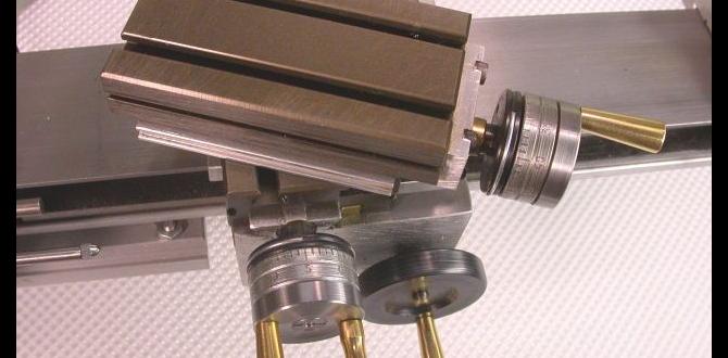
3. Tool Selection: Diameter and Flute Count
For G10, especially when using a TiAlN 35-degree ball nose end mill:
- Diameter: Choose the smallest diameter that fits your design. Smaller diameters allow for tighter radii and more detail. Common sizes include 1/8″, 3/16″, and 1/4″. Ball nose mills are specified by their diameter (e.g., 1/4″ ball nose) and this refers to the diameter of the ball tip.
- Flute Count: 2-flute or 4-flute tools are generally best for G10.
- 2-Flute: Excellent for general machining of composites. Offers good chip clearance and a good balance of feed rate and surface finish. Often the preferred choice for G10.
- 4-Flute: Can provide a smoother finish with very light cuts but may struggle with chip evacuation in deeper cuts.
4. Tool Path Strategies
How you program your cuts matters immensely for preventing issues:
- Climb Milling vs. Conventional Milling: For G10, climb milling is almost always preferred. In climb milling, the cutter rotates in the same direction as its feed movement. This results in a shearing action that pulls the chip off cleanly, reduces friction, and minimizes the chance of chipping. Conventional milling, where the cutter rotates against the direction of feed, can push material away and cause more tear-out.
- Spring Passes: On G10, especially for critical dimensions, taking a final “spring pass” with a very light depth of cut (e.g., 0.001″ – 0.002″) and a slightly faster feed can help clean up any slight inaccuracies or fuzziness left by previous passes.
- Contain Pockets: When milling pockets, ensure your tool path fully contains the cut area and that the lead-in/lead-out ramps cleanly into the material to avoid gouging the workpiece.
A great resource for understanding milling strategies and parameters is the National Institute of Standards and Technology (NIST) Manufacturing Extension Partnership (MEP). They have various guides and research papers on machining best practices. For instance, understanding chip load from sources like the NIST MEP can significantly improve your results: NIST MEP.
Table: Tooling Comparison for G10 Machining
To help you see why the TiAlN 35-degree ball nose is a standout, here’s a comparison:
| Tool Type | Coating | Helix Angle | Best For G10 | Potential Issues with G10 |
|---|---|---|---|---|
| Ball Nose End Mill | Uncoated Carbide | 30° – 45° | Basic contouring, softer G10 batches. | Rapid wear, chipping, melts easily due to heat. |
| Ball Nose End Mill | TiN (Titanium Nitride) | 30° – 45° | Better heat resistance than uncoated. | Still prone to wear and melting under high heat & friction. |
Ball
Related Posts |