Summary: For machining cast iron, a TiAlN ball nose end mill is essential. Its special coating handles cast iron’s hardness and heat, preventing tool wear and ensuring smooth, precise cuts for complex shapes like fillets and pockets.
So, you’re looking to machine cast iron and want to get the best results? It can be a bit tricky, as cast iron can be tough on your cutting tools. You might be seeing a lot of talk about specific types of end mills, and one that keeps popping up is the TiAlN ball nose end mill. If you’re wondering if it’s truly essential, especially for intricate work, you’re in the right place. We’re going to break down exactly why this tool is so good for cast iron, what makes it special, and how even a beginner can use it effectively to create those smooth, flowing shapes without all the frustration. Let’s get started on mastering cast iron machining!
Why Cast Iron is Special (and Demanding!) for Machining
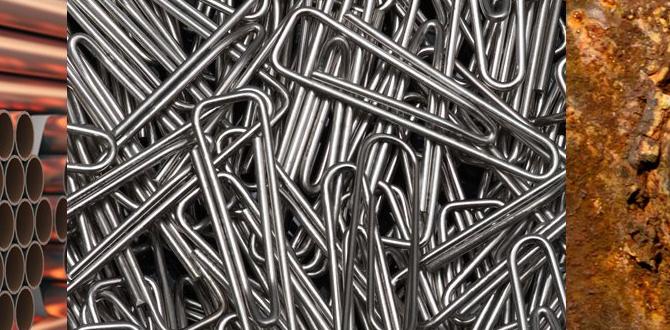
Cast iron might seem like just a heavy, gray metal, but machining it presents some unique challenges. It’s a family of iron-carbon alloys with carbon content typically above 2%. This high carbon content gives it desirable properties like good wear resistance and excellent damping of vibrations, which is great for things like machine bases. However, it also means cast iron can be brittle and abrasive.
When you try to cut cast iron with the wrong tool, you’ll quickly run into problems. The abrasive nature of the iron can wear down standard cutting edges rapidly. The heat generated during machining can also cause built-up edge, where softened material welds onto your tool, ruining your cut and potentially damaging your workpiece. For complex shapes, like those found in mold making or specialized machine parts, precision and a smooth finish are crucial. This is where the right tooling, like a TiAlN ball nose end mill, really shines.
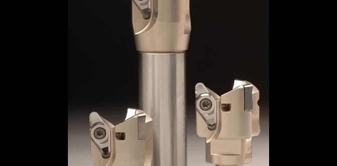
What Exactly is a Ball Nose End Mill?
Before we dive into the ‘TiAlN’ part, let’s understand the ‘ball nose’ aspect. A ball nose end mill, also known as a radius end mill, has a cutting tip shaped like the end of a ball. This means the cutting edge is rounded, forming a hemispherical shape at the tip.
Why is this shape so useful? Unlike flat-bottomed end mills, a ball nose end mill can:
Create radiused corners (fillets): This is perfect for avoiding stress concentrations in parts. Sharp corners are weak points; curves distribute stress better.
Machine complex 3D surfaces: The rounded tip allows for smooth, continuous cuts on contoured shapes, common in die and mold making.
Perform slotting and profiling: While not its primary use, it can be used for these tasks when a radiused corner is desired.
Achieve a good surface finish: The continuous round profile can often leave a smoother finish than multi-fluted flat end mills when used correctly.
Imagine carving a smooth scoop out of something – that’s the kind of motion a ball nose end mill excels at. For beginners, this forgiving shape can be easier to control for creating smooth transitions.
The Magic Behind TiAlN: A Special Coating for Tough Jobs
Now, let’s add the ‘TiAlN’ to the mix. TiAlN stands for Titanium Aluminum Nitride. This is a very hard and durable thin coating that’s applied to the cutting tool’s surface, usually through a Physical Vapor Deposition (PVD) process.
What does this TiAlN coating do for your end mill, and why is it so good for cast iron?
Extreme Hardness: TiAlN is significantly harder than the base material of the end mill. This hardness allows it to resist wear and abrasion, especially from hard materials like cast iron.
High-Temperature Resistance: Cast iron machining generates a lot of heat. TiAlN forms a ceramic-like layer at high temperatures, which acts as a barrier. This prevents the cutting edge from softening and degrading, allowing for higher cutting speeds and feeds without damaging the tool.
Reduced Friction: The coating creates a smoother surface on the tool, which reduces friction between the tool and the workpiece. Less friction means less heat and less chance of material welding onto the cutter (built-up edge).
Oxidation Resistance: TiAlN has excellent resistance to oxidation, meaning it won’t break down when exposed to high temperatures in the air during cutting.
Think of the coating like a super-tough shield for your end mill. It allows the tool to cut more aggressively and for longer periods, especially in materials that would quickly dull or destroy a standard uncoated tool. For cast iron, this is crucial because the material is both abrasive and can generate significant heat.
TiAlN Ball Nose End Mills: The Dynamic Duo for Cast Iron
Combining the rounded shape of a ball nose end mill with the robust TiAlN coating creates a tool that’s exceptionally well-suited for machining cast iron, especially for applications demanding precision and complex geometry.
Here’s why this combination is often called “essential” for cast iron:
Superior Surface Finish: The smooth, rounded cutting edge coupled with the low-friction surface of the TiAlN coating allows for excellent surface finishes on cast iron. This is vital for parts that need to fit together precisely or operate smoothly.
Extended Tool Life: Cast iron can chew up standard tools quickly. The TiAlN coating significantly extends the life of the ball nose end mill, meaning fewer tool changes and more consistent results over time. This is a big win for productivity and your wallet.
High-Speed Machining Capabilities: thanks to the heat resistance of TiAlN, you can often push your cutting speeds and feed rates higher when machining cast iron with these tools. This can drastically reduce machining time.
Ideal for 3D Contouring and Helical Interpolation: The ball nose shape is perfect for creating smooth, flowing surfaces. When combined with TiAlN, it can perform these operations reliably on cast iron, which is a demanding task. For operations like helical interpolation for cast iron, a TiAlN ball nose end mill provides the necessary durability and precision.
Reduced Risk of Heat-Related Tool Failure: For beginners, this means less worry about overheating and ruining the tool or the workpiece. The coating helps manage the heat, making the process more forgiving.
Consider applications like making molds for plastic injection, intricate engine parts, or decorative components. These often involve complex curves and require a good finish on cast iron. A TiAlN ball nose end mill is the go-to tool for these jobs.
Key Features to Look For in a TiAlN Ball Nose End Mill for Cast Iron
When you’re heading out to get your first TiAlN ball nose end mill for cast iron, there are a few specific features that will make your life easier and your machining better.
Helix Angle
The helix angle refers to the angle of the flutes (the spiral grooves on the cutter). For cast iron, you’ll often find these end mills available in different helix angles:
High Helix Angle (e.g., 45-60 degrees): These are generally excellent for cast iron. A higher helix angle results in a more shearing cutting action, which helps to break up chips into smaller pieces. This is good for cast iron as it can be stringy and hard to manage. High helix also provides a smoother finish and reduces the tendency for chatter.
Standard Helix Angle (e.g., 30 degrees): This is a more general-purpose angle. While it can work, a higher helix angle is usually preferred for cast iron’s abrasive nature.
Zero or Low Helix Angle: These are typically not recommended for cast iron, as they can lead to poor chip evacuation and increased heat.
For cast iron, especially when focusing on helical interpolation for cast iron, a high helix angle end mill is often the preferred choice to manage chips and heat effectively.
Number of Flutes
The number of flutes (cutting edges) on an end mill affects its performance:
2-Flute End Mills: These are great for plunging (drilling into material) and slotting. They offer good chip clearance, which is important for materials like cast iron that can produce tough chips. For profiling and contouring in cast iron, a 2-flute end mill is often a good choice.
3-Flute End Mills: These offer a good balance between chip clearance and the ability to take a heavier cut than a 4-flute. They are also quite versatile.
4-Flute End Mills: These are generally used for finishing operations and taking lighter cuts. They provide a smoother finish but have less chip clearance. For cast iron, using a 4-flute for aggressive material removal might lead to chip packing and overheating. However, for a final finishing pass, a 4-flute can deliver an excellent surface.
For general work and helical interpolation in cast iron, a 2-flute or 3-flute TiAlN ball nose end mill is often recommended to ensure good chip evacuation.
Material of the End Mill (Substrate)
While the coating is critical, the base material (substrate) of the end mill also matters. For cast iron, you’ll typically want an end mill made from:
Solid Carbide: This is the most common and highly recommended material for end mills used in cast iron. Carbide is very hard and can withstand the high cutting forces and temperatures involved.
High-Speed Steel (HSS): While HSS can be coated with TiAlN, it’s generally not as rigid or heat-resistant as carbide. For demanding cast iron applications, solid carbide is superior.
Always look for solid carbide end mills when machining cast iron for the best performance and longevity.
Diameter and Radius
The diameter of the end mill and the radius of its tip will depend entirely on the geometry you need to create.
Diameter: Choose a diameter that fits the smallest feature you need to machine.
Radius: The radius of the ball nose should match the desired fillet radius in your design. Make sure the radius is proportional to the diameter – a very small radius on a large diameter end mill can be weak.
When performing operations like making a 40-degree fillet with a ball nose end mill in cast iron, you’ll select an end mill with a corresponding radius.
Example Table: Recommended TiAlN Ball Nose End Mill Features for Cast Iron
| Feature | Recommendation for Cast Iron | Why It’s Important |
| :—————- | :—————————————————- | :————————————————————– |
| Coating | TiAlN (Titanium Aluminum Nitride) | Excellent hardness and heat resistance for abrasive cast iron. |
| Substrate | Solid Carbide | Superior rigidity, hardness, and heat tolerance. |
| Helix Angle | High Helix (45-60 degrees) | Promotes shearing action, better chip control, smoother finish. |
| Number of Flutes | 2 or 3 Flutes (for general use/roughing/helical ops) | Optimizes chip clearance, prevents chip packing. |
| | | 4 Flutes (for finishing passes) |
| Shape | Ball Nose (Radius End Mill) | Creates radiused corners and complex contoured surfaces. |
Step-by-Step Guide: Machining Cast Iron with a TiAlN Ball Nose End Mill
Alright, let’s get practical! Here’s a beginner-friendly guide on how to use your TiAlN ball nose end mill to machine cast iron. We’ll cover setup, basic machining principles, and safety.
Step 1: Prepare Your Workpiece and Machine
Secure the Workpiece: Ensure your cast iron workpiece is firmly clamped or fixtured on your milling machine. Use appropriate clamping methods that won’t distort the part. For critical dimensions, consider using parallels or supports to keep the workpiece stable.
Clean the Machine: Before you start, ensure your milling machine is clean. Remove any debris from the table, vise, and spindle.
Install the End Mill: Mount the TiAlN ball nose end mill securely in your collet or tool holder. Make sure it’s seated properly and tightened. Overtightening can damage the collet or the end mill shank.
Step 2: Set Up Your Cutting Parameters (Speeds & Feeds)
This is where many beginners get anxious, but it’s simpler than it sounds. For cast iron with a TiAlN coated carbide end mill, you’ll generally want to use:
Spindle Speed (RPM): Cast iron can be cut effectively at moderate to high speeds. A good starting point for solid carbide end mills in cast iron is often in the range of 300-800 SFM (Surface Feet per Minute). To convert this to RPM, you can use the formula:
RPM = (SFM 12) / (π Diameter)
Example: For a 1/2 inch diameter end mill, at 400 SFM:
RPM = (400 12) / (3.14159 0.5) ≈ 3056 RPM.
Always consult the tool manufacturer’s recommendations if available.
Feed Rate (IPM – Inches Per Minute): The feed rate determines how fast the tool moves through the material. This is closely related to the chip load, which is the thickness of material removed by each cutting edge. For cast iron, aim for a moderate chip load to avoid chatter and ensure good chip formation. A starting point might be 0.002 – 0.005 inches per tooth.
Feed Rate (IPM) = Chip Load (inches/tooth) Number of Flutes RPM
Example: For a 2-flute end mill at 3000 RPM, with a chip load of 0.003″:
Feed Rate = 0.003 2 3000 = 180 IPM.
Depth of Cut (DOC): For best results and to manage heat and chip load, take lighter cuts. A radial depth of cut (how much of the tool’s diameter is engaged) of 20-50% is common for profiling. For axial depth of cut (how deep the tool cuts into the material), start conservatively, perhaps 0.1-0.2 times the tool diameter, and observe the cut.
Important Tip: Always start with conservative parameters. Listen to the sound of the cut. A smooth, consistent sound is good. A chattering or screaming sound indicates something is wrong – usually too high a feed, too shallow a depth of cut, or tool deflection.
Step 3: Set Your Z-Axis Zero and XY Origin
Z-Axis Zero: Carefully bring the tip of the ball nose end mill down to the top surface of your workpiece (or your datum surface). Use a touch probe, edge finder, or dial indicator to find your Z-zero. Most CAM software and CNC controllers will use this as your reference point for cutting depth.
XY Origin: Similarly, set your XY zero point. This is typically a corner of your workpiece or a specific feature you’ve designed your part around.
Step 4: Perform the Machining Operation
Coolant/Lubrication: For cast iron, running dry is often preferred, as coolant can sometimes cause issues with chip packing or create a muddy mess. If you use coolant, a copious amount of a flood coolant is better than a mist. Air blast is also a good option for chip evacuation.
Engage the Spindle: Start the spindle to your calculated RPM.
Begin the Cut: Engage the Z-axis feed to perform your plunge or initial entry. Then, engage the X or Y-axis feed to begin your contouring or slotting operation.
Observe the Cut: Pay close attention to the chips being produced, the sound of the cutting, and the surface finish.
Chip Evacuation: Are the chips breaking up nicely and clearing away from the cutting area? If they are long and stringy, your feed rate might be too low, or your helix angle might not be optimal.
Sound: A consistent, light singing sound is good. Harsh grinding or chatter means you need to adjust your parameters.
Surface Finish: Is your ball nose end mill leaving a smooth, consistent surface? If you see tool marks or scallops that are too large, you might need to adjust your stepover or depth of cut.
Step 5: Helical Interpolation (a Common Use Case)
Helical interpolation is a great way to create internal cylindrical or spherical features, or to clear out a large pocket with a radiused bottom. With a ball nose end mill, you can achieve this by commanding the machine to move in a circular path while simultaneously feeding downwards.
1. Program the Helix: This is usually done via G-code or through CAM software. You’ll define the center of your circle, the radius, the desired RPM, and the feed rate for the downward motion.
2. Start with a Plunge: Often, you’ll need to plunge the end mill into the material to a certain depth before the helical motion begins. With a ball nose, this is relatively easy.
3. Execute the Helix: The machine controller then commands simultaneous motion in X, Y, and Z to create the helical path.
4. Finish the Feature: Once the desired depth is reached, you might perform a finishing pass or leave it as is, depending on the required accuracy and finish.
The TiAlN coating and the ball nose shape are critical here to handle the continuous engagement with the cast iron while creating a smooth, precise internal profile.
Step 6: Finishing Touches and Inspection
Retract the Tool: Once the machining is complete, retract the end mill out of the workpiece.
Clean the Part: Remove any residual chips or swarf from the workpiece.
* Inspect: Check your machined feature for accuracy, surface finish, and any signs of tool wear or defects.