This guide provides a straightforward, step-by-step process for replacing the motor wiring on your wood lathe, ensuring a safe and successful upgrade for hobbyists and home workshop owners. Learn how to re-energize your lathe with confidence.
Is your wood lathe motor making strange noises, humming but not turning, or worse, completely unresponsive? A faulty motor is a common frustration for wood turners, but don’t let it put your projects on hold. Replacing the motor wiring might sound intimidating, but with a clear guide, it’s a manageable task for any DIY enthusiast. We’re here to walk you through each step, making sure you can safely and effectively get your lathe humming like new. Let’s dive in and bring your lathe back to life!
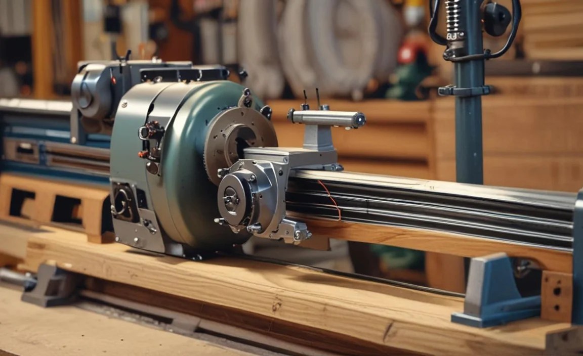
Wood Lathe Motor Replacement Wiring: Proven Guide

Welcome to the heart of your wood lathe – the motor. This powerful component drives all your turning projects. However, like any electrical component, a wood lathe motor can eventually wear out or its wiring can become damaged over time. Whether your motor has failed, you’re upgrading to a more powerful one, or you’ve simply found some worn wiring, replacing the motor and its associated wiring is a crucial maintenance task. This guide is designed to break down the process, making it accessible even if you’re new to motor replacement.
We’ll cover everything from identifying the right replacement motor to safely disconnecting the old wiring and connecting the new. Our goal is to ensure you can complete this task with confidence, keeping safety and reliability at the forefront. By the end of this article, you’ll have a working wood lathe and the knowledge to tackle similar electrical tasks in your workshop.
Why Replace Wood Lathe Motor Wiring?

Several factors can necessitate replacing the wiring of your wood lathe motor. Understanding these reasons will help you identify potential issues early and appreciate the importance of a proper replacement.
- Electrical Component Failure: Motors, especially in demanding workshop environments, can suffer from internal failures. If the motor itself is beyond repair, a replacement, complete with new wiring, is the logical next step.
- Worn or Damaged Insulation: Over time, insulation on motor wires can become brittle, cracked, or frayed due to heat, vibration, or physical damage. This is a significant safety hazard, increasing the risk of short circuits or electric shock.
- Outdated or Inadequate Wiring: Older lathes might have wiring that doesn’t meet current safety standards or is insufficient for a more powerful motor you might be installing. Upgrading to modern, appropriately gauged wiring ensures optimal performance and safety.
- Upgrades and Performance Improvements: You might be installing a new, more powerful motor to enhance your lathe’s capabilities. This often requires new wiring that can handle the increased power load.
- Troubleshooting Persistent Issues: If your lathe is exhibiting intermittent power issues, overheating, or strange noises that aren’t due to mechanical problems, the wiring might be the culprit. Replacing it can resolve these nagging problems.
Choosing the Right Replacement Motor and Wiring

Before you start disconnecting anything, selecting the correct replacement motor and wiring is paramount. This involves understanding your lathe’s specifications and the requirements for safe operation.
Matching Motor Specifications
When selecting a new motor, it’s essential to match it to your lathe’s existing mounting points and power requirements. Consider these factors:
- Horsepower (HP): Ensure the new motor’s horsepower is compatible with your lathe. Going too high without considering the lathe’s structure can be problematic, while too low might limit functionality. A common range for hobbyist lathes is 1/2 HP to 1 HP.
- Voltage: Most wood lathes run on standard household voltages (110-120V or 220-240V). Make sure your new motor matches your workshop’s electrical supply.
- Amperage (Amps): This indicates how much current the motor draws. It’s crucial for selecting the correct wiring gauge and circuit breaker.
- RPM (Revolutions Per Minute): The motor’s speed, often variable, affects turning capabilities.
- Mounting Dimensions: The physical size and bolt pattern of the motor must fit your lathe’s motor mount.
Selecting Appropriate Wiring
The wiring connecting the motor to its power source is just as critical as the motor itself. Using the wrong gauge wire can lead to overheating, reduced efficiency, and fire hazards.
| Motor Amperage (Approx.) | Recommended Wire Gauge (AWG) | Maximum Distance (for each conductor) |
|---|---|---|
| < 10 Amps | 14 AWG | 50 feet |
| 10 – 15 Amps | 12 AWG | 50 feet |
| 15 – 20 Amps | 10 AWG | 50 feet |
| 20 – 30 Amps | 8 AWG | 50 feet |
Note: Always consult the National Electrical Code (NEC) or your local electrical codes for the most accurate and up-to-date wiring requirements. For any wiring exceeding 50 feet, you may need to use a heavier gauge wire. Consider purchasing a pre-wired motor, or if wiring separately, ensure you have appropriate wire connectors (like wire nuts or crimp connectors) and heat shrink tubing for secure, insulated connections.
For further details on electrical wiring standards, the National Electrical Code (NEC) offered by the National Fire Protection Association is an essential resource.
Tools and Materials Needed
Gathering the right tools and materials before you begin will make the entire process smoother and safer.
- Safety glasses
- Work gloves
- Screwdriver set (Phillips and flathead)
- Socket set or wrenches (to remove motor mounting bolts)
- Wire strippers/cutters
- Pliers
- Multimeter (for testing continuity and voltage)
- Non-contact voltage tester
- New replacement motor (if applicable)
- Appropriate gauge electrical wire (if not pre-wired)
- Wire connectors (wire nuts, spade connectors, etc.)
- Heat shrink tubing and a heat gun/lighter
- Electrical tape (high-quality, rated for voltage)
- Cable ties or zip ties (for wire management)
- Owner’s manual for your wood lathe (highly recommended)
Step-by-Step: Replacing Wood Lathe Motor Wiring

Safety is the absolute priority when working with electrical components. Always ensure power is completely disconnected before commencing any work.
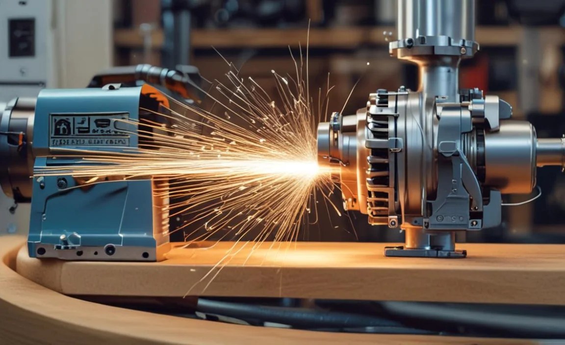
Step 1: Disconnect Power and Safety First

This is the MOST critical step. Before you touch anything:
- Unplug the Lathe: Ensure the power cord is completely removed from the wall outlet.
- Double-Check: If your lathe has a power switch, turn it off. Then, use a non-contact voltage tester at the power switch and at the motor connection point (if accessible externally) to confirm there is no power.
- Wear Safety Gear: Put on your safety glasses and work gloves.
Never assume power is off. Always test.
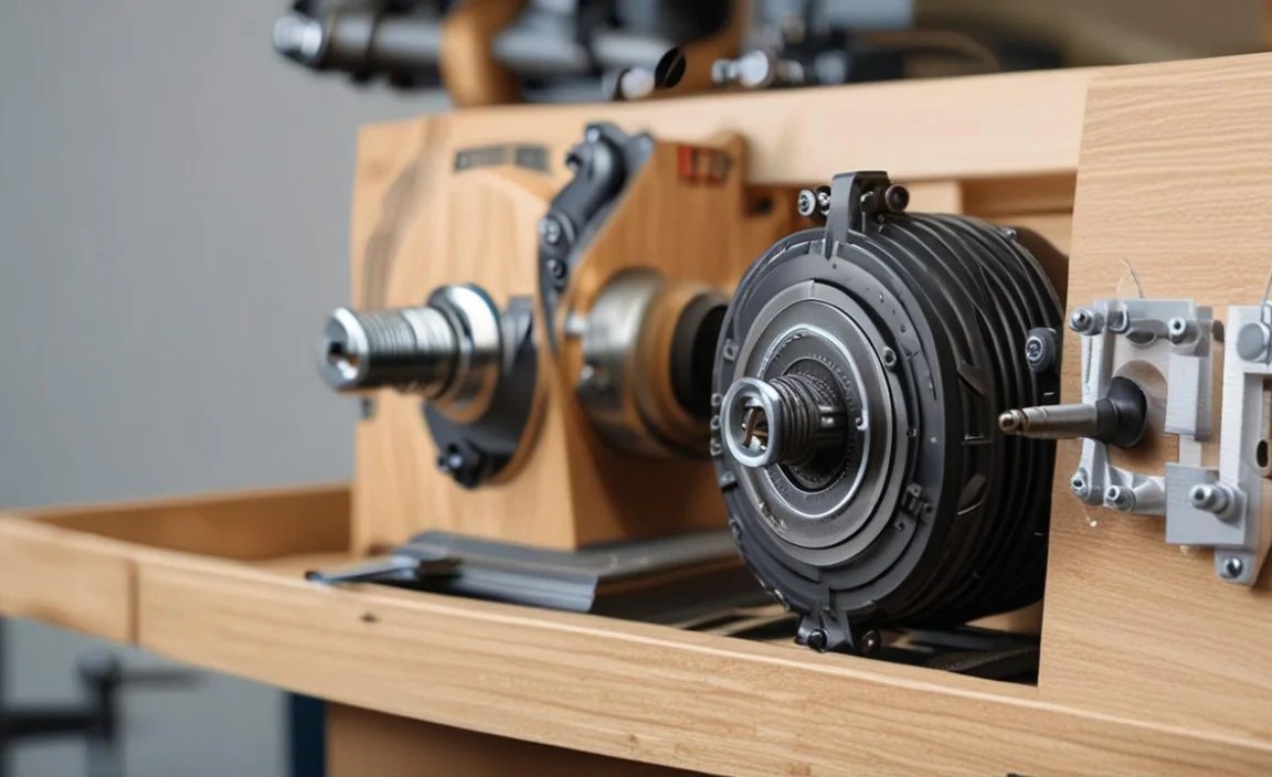
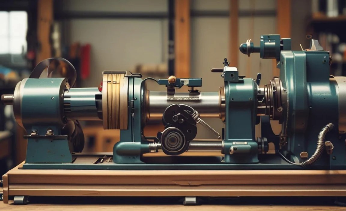
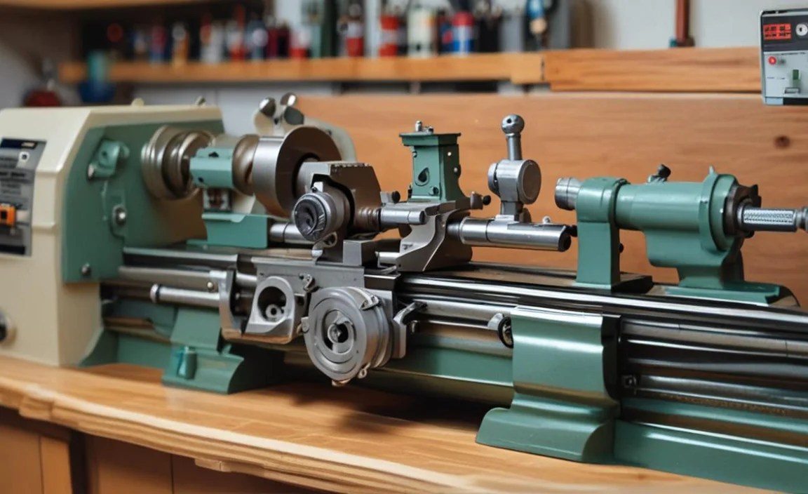
Step 2: Access the Motor and Wiring

Locate the motor on your wood lathe. It’s usually housed within a protective casing or integrated into the lathe’s stand.
- Open Motor Housing: You may need to remove screws or panels to access the motor and its electrical connections. Refer to your lathe’s owner’s manual if you’re unsure how to open the housing.
- Identify Existing Wiring: Observe how the current wiring is connected to the motor terminals and to the lathe’s power switch or control box. Take pictures or make detailed notes. You’ll want to replicate these connections precisely. Note any color coding or terminal labels (e.g., L for Line, N for Neutral, G for Ground; or T1, T2, T3 for motor windings if it’s a 3-phase motor, though most wood lathes are single-phase AC).
Step 3: Disconnect the Old Wiring

Once you have a clear view of the connections:
- Motor Terminals: Carefully disconnect the wires from the motor’s terminal block or connection points. This might involve unscrewing terminals, releasing spade connectors, or cutting wire nuts.
- Control Box/Switch: Disconnect the wires leading from the motor to the lathe’s power switch or speed control. Again, take photos to help with reassembly.
- Ground Wire: Crucially, ensure the ground wire (typically green or bare copper) is disconnected properly. This wire is vital for safety.
Step 4: Remove the Old Motor (If Replacing Motor Too)

If you are also replacing the motor:
- Mounting Bolts: Locate and remove the bolts securing the motor to its mount on the lathe. You might need to support the motor’s weight as you remove the last bolt.
- Belt Removal: If your lathe has a belt drive, you’ll need to remove the belt from the motor pulley before lifting the motor free.
Step 5: Install the New Motor (If Applicable)

If you’re installing a new motor:
- Mounting: Carefully position the new motor onto the lathe’s mount. Re-install and tighten the mounting bolts securely.
- Pulley Alignment: Ensure the pulley on the new motor is aligned with the headstock or counter-shaft pulley.
- Belt Installation: Re-install the drive belt, ensuring proper tension. Check your manual for recommended belt tension.
Step 6: Connect the New Wiring

This is where your notes and photos from Step 2 become invaluable. If your new motor came pre-wired, this step might involve connecting the integrated wiring harness to your lathe’s control system.
- Motor Terminals: Connect the appropriate wires from your lathe’s power supply/switch to the corresponding terminals on the new motor.
- Line/Hot (L): Connects to the switched power source.
- Neutral (N): Connects to the neutral line.
- Ground (G): Connects to the ground terminal or screw on the motor and the lathe’s chassis. This is absolutely essential for safety. Ensure a solid connection.
Refer to your motor’s wiring diagram, which should be attached to it or included in its documentation. Most single-phase AC motors have simple L, N, and G connections. Complex multi-speed motors may have additional terminals (like T1, T2, T3) for different winding configurations.
- Secure Connections: Use high-quality wire connectors. For wire nuts, ensure they are sized correctly for the number and gauge of wires you are joining. Twist wires tightly before applying the connector. For spade connectors, ensure they make firm contact with the terminal.
- Insulate Properly: After making connections, use heat shrink tubing over the connectors and wires for added insulation and strain relief. If heat shrink isn’t used, wrap connections with high-quality electrical tape securely, overlapping layers to prevent moisture ingress and abrasion.
- Manage Wires: Use cable ties or conduit to neatly route and secure the wiring. Prevent wires from dangling where they could be snagged by the workpiece or lathe components, or abraded against sharp edges. Ensure there’s enough slack for any motor movement if it’s on a swiveling base.
Step 7: Test the Wiring and Motor

Before fully reassembling, it’s time for a crucial test.
- Visual Inspection: Double-check all connections. Ensure no bare wire is exposed where it shouldn’t be and that all terminals are tight. Make sure wires are routed safely away from moving parts.
- Continuity Test (Optional but Recommended): If you have a multimeter, you can check for continuity between terminals and ensure no short circuits exist. For example, check continuity between the Line and Neutral terminals – it should be very low resistance. Check between Line/Neutral and Ground – there should be no continuity. Always perform these tests with power OFF.
- Power Up Safely: Reconnect the power cord, but keep the motor housing cover off for this initial test. Stand clear and turn on the power switch.
- Observe: Does the motor run? Does it spin in the correct direction (typically clockwise when viewed from the motor shaft end for most applications)? Listen for any unusual noises. Test the speed control if your lathe has one.
- Check Rotation Direction: If the motor spins the wrong way for a single-phase motor, you can often reverse it by swapping the connections to the start winding or capacitor terminals, or by reversing the two “Line” leads where they connect to the internal motor terminals (consult your motor’s manual). Important: This only applies to specific types of single-phase motors. Always consult your motor’s documentation.
Step 8: Final Assembly and Testing
Once you’ve confirmed the motor is running correctly and in the right direction:
- Secure Housing: Turn off the power again and unplug the lathe. Reinstall any motor housing covers or panels that you removed.
- Full Power Test: Plug the lathe back in and run it for a few minutes at different speeds. Listen for the motor. Feel the motor housing carefully—it should be warm, but not excessively hot. Check for any vibrations.
- Test Accessories: If your lathe has variable speed control or other features, test them thoroughly.
Troubleshooting Common Issues
Even with a detailed guide, you might encounter a snag. Here are a few common problems and how to address them:
- Motor Humms but Doesn’t Spin: This often indicates a start winding failure or a capacitor issue. If you’ve replaced the wiring, the problem likely lies within the motor itself. For single-phase motors, this could also mean the start winding is shorted or open.
- Motor Runs Backwards: As mentioned in Step 7, for single-phase motors, you can usually reverse rotation by swapping specific internal wiring connections. Consult your motor’s manual for the correct procedure.
- No Power to Motor: Check the power cord, the switch, and all connections up to the motor. Use your multimeter to trace the path of the electricity. Ensure the circuit breaker controlling the outlet hasn’t tripped.
- Motor Overheats: This could be due to undersized wiring, a struggling motor (e.g., trying to turn too large a piece), or a motor that is simply failing. Ensure your wiring gauge is appropriate for the motor’s amperage draw.
- Intermittent Power: Loose connections are the most common cause of intermittent power. Re-check all wire connections, ensuring they are tight and secure, especially at the motor terminals and switch.
For more in-depth troubleshooting of motor-specific issues, resources like ElectricHelp.com forums offer a wealth of community knowledge and expert advice on motor diagnostics.
Frequently Asked Questions (FAQ)
Q1: How do I know if my wood lathe motor needs rewiring?

A1: Signs include frayed or cracked insulation on wires, the motor humming but not turning, a burning smell, or consistent electrical faults. If you notice any damage to the existing wiring, replacement is a good idea for safety and reliability.
Q2: Can I use standard household wire for my wood lathe motor?

A2: You must use wire that is rated for the appropriate voltage and amperage of your motor and is of the correct gauge (AWG). Using standard, undersized wire can lead to overheating and fire hazards. Always consult wiring charts and local electrical codes.
Q3: What is the most critical safety precaution when replacing motor wiring?

A3: The most critical step is ensuring the power is completely disconnected at the source (unplugged) and verified with a voltage tester before touching any wires or components. Always wear safety glasses and gloves.
Q4: My new motor spins the wrong way. How can I fix this?

A4: For most single-phase AC motors, you can reverse the direction by swapping the connections to the start winding or capacitor terminals, or by reversing the two “Line” leads where they connect internally. Consult your motor’s specific wiring diagram or manual for the correct.
