Quick Summary: Unlock the secrets to perfect 3/16 inch face milling on 6061 aluminum with the right feeds and speeds. This guide provides essential parameters to achieve smooth finishes, efficient cuts, and extend tool life for your milling projects.
Mastering 3/16″ Face Milling on 6061 Aluminum: A Beginner’s Guide
Choosing the right settings for your milling machine can feel like a puzzle, especially when you’re just starting out. It’s easy to get overwhelmed by numbers and jargon. But what if I told you that getting a beautiful, clean finish on 6061 aluminum with a 3/16 inch face mill is totally achievable? Many beginners worry about damaging their tools or ruining their workpiece. Don’t let those concerns hold you back! In this guide, Lathe Hub’s Daniel Bates will walk you through exactly what you need to know to confidently tackle face milling 6061 aluminum. We’ll break down the essential feeds and speeds, making it simple and straightforward. Get ready to mill like a pro!
Why Feeds and Speeds Matter for Aluminum
In the world of milling, “feeds and speeds” are the two most critical factors that determine the success of a cut. They dictate how fast your tool spins (spindle speed) and how quickly it moves through the material (feed rate). Getting these just right for 6061 aluminum is key. This alloy is known for being easy to machine, but it can also be “gummy” if you’re not careful. This means it can load up your cutting tool, leading to poor finishes, broken tools, and frustration.
When you get your feeds and speeds dialed in, you’re not just saving time; you’re also:
- Achieving a smoother surface finish on your parts.
- Reducing the chance of tool breakage.
- Extending the useful life of your cutting tools.
- Making your milling operations more efficient and less stressful.
- Ensuring your parts are dimensionally accurate.
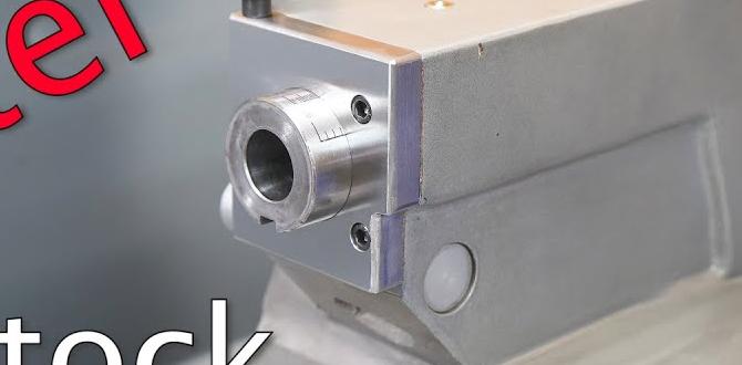
Understanding Your Cutting Tool: The 3/16″ Face Mill

For this guide, we’re focusing on a 3/16 inch face mill. This tool is great for taking rapid material removal across a flat surface. Face mills come in various designs, but for beginners, a common type will have multiple cutting edges (inserts or solid carbide teeth) that rotate around a central point.
Key things to consider about your 3/16″ face mill:
- Material: Is it solid carbide? High-speed steel (HSS)? Most modern face mills for general aluminum work are solid carbide.
- Number of Teeth (or Inserts): More teeth can mean faster material removal, but they also require more power and generate more heat.
- Coating: Some carbide tools have coatings (like TiN or AlTiN) that improve performance and tool life, especially on tougher materials. For aluminum, uncoated or specialized aluminum coatings are often best to prevent “sticking.”
- Insert Geometry (if applicable): The shape and rake angle of the cutting edges are designed for specific materials.
For 6061 aluminum, a well-sharpened solid carbide 3/16″ face mill is an excellent choice. Its hardness and ability to hold an edge make it suitable for this alloy.
Why 6061 Aluminum is Popular (and what to watch out for)
6061 aluminum is one of the most widely used aluminum alloys, and for good reason. It’s:
- Strong: It offers good strength-to-weight ratios.
- Corrosion Resistant: It holds up well against rust and other forms of corrosion.
- Weldable: It can be welded using standard aluminum welding techniques.
- Machinable: This is where it really shines! It’s known for being easy to cut and shape.
However, because it’s relatively soft and “gummy,” it can present some machining challenges if you’re not precise with your feeds and speeds. The chief concern is “chip welding,” where the aluminum chips stick to the cutting edges of your tool. This can lead to:
- Poor surface finish.
- Increased cutting forces, potentially damaging your machine or tool.
- Tool failure due to overheating and excessive load.
Correct feeds and speeds, along with proper chip evacuation (coolant/air blast), are your best defense against these issues.
Calculating Essential Feeds and Speeds

This is where the rubber meets the road! We need to determine appropriate settings for your 3/16″ face mill on 6061 aluminum. The key components are Surface Speed and Chip Load.
Surface Speed (SFM or m/min)
Surface speed is the linear speed of the cutting edge of your tool as it moves across the workpiece. It’s usually expressed in surface feet per minute (SFM) or meters per minute (m/min). Different tool materials have different optimal surface speed ranges.
For uncoated solid carbide tools cutting 6061 aluminum, a good starting range is typically:
- 600 – 1200 SFM (Surface Feet per Minute)
To convert this to your machine’s Spindle Speed (RPM), you’ll use the following formula:
RPM = (Surface Speed (SFM) 3.82) / Tool Diameter (inches)
The “3.82” is a constant that accounts for pi and unit conversions.
Chip Load (IPT or mm/tooth)
Chip load refers to the thickness of the material each cutting tooth removes as it passes through the workpiece. It’s measured in inches per tooth (IPT) or millimeters per tooth (mm/tooth). This is CRITICAL for preventing chip welding in aluminum.
For a 3/16″ solid carbide face mill on 6061 aluminum, a good starting chip load range is:
- 0.001″ – 0.003″ IPT (Inches Per Tooth)
The exact chip load will depend on the number of teeth on your face mill, the depth of cut, and the rigidity of your setup. Always start on the lower end of this range and increase if the cut is smooth and the chips look good.
Spindle Speed (RPM) Calculation Example
Let’s put it into practice. Suppose you have a 3/16″ (0.1875″) solid carbide face mill and you want to run it at 800 SFM.
Calculation: RPM = (800 SFM 3.82) / 0.1875 inches
Result: RPM ≈ 16,320 RPM
Hold on! That’s a very high RPM. Many common benchtop milling machines might not reach this speed. This is where we adjust. If your machine has a top speed of, say, 10,000 RPM, you need to find the SFM that corresponds to that speed for your tool diameter:
Surface Speed (SFM) = (RPM Tool Diameter (inches)) / 3.82
Using 10,000 RPM:
Calculation: SFM = (10,000 RPM 0.1875 inches) / 3.82
Result: SFM ≈ 490 SFM
This SFM (490) is a bit lower than our ideal range (600-1200 SFM), but it’s a good compromise for many machines. Running at this SFM is better than not being able to mill at all.
Feed Rate (IPM or mm/min) Calculation
Once you know your spindle RPM and your desired chip load per tooth, you can calculate your feed rate in inches per minute (IPM).
Feed Rate (IPM) = Spindle Speed (RPM) Number of Teeth (Z) Chip Load (IPT)
Let’s assume:
- Spindle Speed: 10,000 RPM (from our previous calculation)
- Number of Teeth (Z): Let’s say your 3/16″ face mill has 4 teeth.
- Chip Load (IPT): We’ll start conservatively at 0.002″ IPT.
Calculation: IPM = 10,000 RPM 4 teeth 0.002 IPT
Result: IPM = 80 IPM
So, for this setup, you’d aim to feed at approximately 80 IPM.
Recommended Feeds and Speeds Table (Starting Points)
Here’s a table to give you a general idea. Remember these are STARTING POINTS. Always listen to your machine and your tool!
| Operation | Material | Tool Diameter | Tool Type | Spindle Speed (RPM) | Surface Speed (SFM) | Chip Load (IPT) | Feed Rate (IPM) | Depth of Cut (DOC) | Notes |
|---|---|---|---|---|---|---|---|---|---|
| Face Milling | 6061 Aluminum | 3/16″ (0.1875″) | Solid Carbide (2-4 Flutes) | 6,000 – 15,000 | 350 – 900 | 0.001 – 0.003 | 36 – 180 (0.001 Z RPM) to (0.003 Z RPM) | 0.010″ – 0.050″ | Start low, listen for cutting sound. Adjust based on machine rigidity and finish. |
Important Considerations for the Table:
- Spindle Speed: This range is dependent on your machine’s capabilities. The lower end is more common for hobbyist machines.
- Surface Speed: The SFM range is typical for carbide. Adjust RPM to achieve this if possible, or use the lower SFM if your machine tops out at lower RPMs.
- Chip Load: Always start at the low end. If chips are fine and clean, you might gradually increase. If chips are getting heavy or you hear chatter, reduce chip load or feed rate.
- Feed Rate: This is calculated based on RPM, number of teeth (Z), and chip load. It’s often the most dynamic setting.
- Depth of Cut (DOC): For aluminum and smaller tools, shallow depths of cut are usually best. Taking too deep a cut will overload the tool and create large, problematic chips. 0.010″ to 0.050″ is a common range.
Factors Influencing Your Feeds and Speeds

The numbers in the table are a guide, but real-world machining involves many variables. Here’s what can affect your settings:
- Machine Rigidity: A wobbly or light-duty machine will vibrate and chatter. You’ll need to run slower feed rates and maybe slower spindle speeds. More rigid machines can handle more aggressive cuts.
- Coolant/Lubrication: Using a coolant or air blast is highly recommended for aluminum. It helps clear chips, reduce heat, and prevent build-up on the tool. This allows for faster spindle speeds and better chip loads. Without it, you’ll likely need to slow down.
- Tool Condition: A sharp, unworn tool will cut cleanly. A dull or chipped tool requires more force and can lead to poor results.
- Workholding: How securely is your workpiece held down? If it can move, you’ll experience chatter. You’ll need to reduce your cut depth and feed rate to compensate for any flex.
- Depth of Cut (DOC): As mentioned, shallower cuts are generally better for aluminum with small tools. Trying to remove too much material at once is a recipe for trouble.
- Tool Engagement: A face mill takes a cut across its entire diameter, but the engagement angle changes. At the entry and exit of the cut, the tool is working harder (and can produce more heat) than when it’s in the center of the cut. Some advanced methods like High-Efficiency Machining (HEM) take this into account, but for beginners, just be aware that the cut isn’t uniform from start to finish.
Step-by-Step: Setting Up for Face Milling Aluminum
Let’s walk through the process to get your 3/16″ face mill working on 6061 aluminum.
-
Prepare Your Machine and Workpiece
Ensure your milling machine is clean and in good working order. Securely fixture your 6061 aluminum workpiece. A solid setup is paramount!
-
Install the Face Mill
Mount your 3/16″ face mill into your machine’s spindle. Ensure it’s seated properly and tightened according to the manufacturer’s recommendations.
-
Determine Your Initial Settings
Based on your machine’s capabilities, your tool, and the recommended table above:
- Choose a target Spindle Speed (RPM).
- Calculate the corresponding Surface Speed (SFM).
- Select a conservative Chip Load (IPT) – e.g., 0.0015″ IPT.
- Calculate your Feed Rate (IPM) using these values and the number of teeth on your tool.
- Set a shallow Depth of Cut (e.g., 0.020″).
Example: For a machine limited to 8,000 RPM:
- Target RPM: 8,000
- Tool: 3/16″ (0.1875″) solid carbide, 4 flutes
- Chip Load: 0.002 IPT
- Calculated SFM: (8000 0.1875) / 3.82 ≈ 393 SFM (This is on the low end, but acceptable if your machine can’t go faster).
- Calculated Feed Rate: 8000 RPM 4 teeth * 0.002 IPT = 64 IPM
- Depth of Cut: 0.020″
-
Engage the Spindle and Coolant
Turn on your spindle to the calculated RPM. If you have a coolant or air blast system, engage it now. It should run throughout the cut.
-
Initiate the Cut
Slowly and smoothly engage the feed rate. Start by feeding into the material. Listen carefully to the sound of the cut.
-
Observe and Adjust
Listen: A smooth, consistent “hissing” or “zipping” sound is good. A loud, chattering, or grinding sound means something is wrong.
Watch: Are the chips coming off cleanly? Are they small and curly, or large and stringy? Are they welding to the tool?
Adjustments:
- Chatter/Noise: Reduce feed rate or depth of cut. Ensure workpiece is secure.
- Chips Welding: Increase chip load slightly, ensure good coolant flow, or decrease spindle speed slightly (which might also decrease SFM). If it’s severe, you may have too high a spindle speed for too low a chip load (too shallow of a cut).
- Poor Finish: Ensure you’re not rubbing. A slight rubbing sound or a dull finish can indicate too low a feed rate or spindle speed.
- Tool Overheating: Ensure adequate coolant. You may need to slow down spindle speed or reduce depth of cut.
-
Complete the Pass
Let the tool complete its pass across the surface. When it’s done, retract the tool smoothly.
-
Inspect and Repeat
Examine your workpiece. Check the surface finish. If you’re happy with the results and the chips looked good, you can consider slightly increasing your chip load or depth of cut for the next pass, or for future operations with identical setups