Carbide end mills, especially 3/16″ ones, are incredibly effective for cutting fiberglass, offering high Material Removal Rates (MRR) for efficient, clean, and fast machining. This guide will show you how to use them safely and effectively.
Working with fiberglass can sometimes feel tricky, especially getting clean cuts without a lot of dust or fraying. If you’ve ever struggled to get a smooth finish or found your tools wearing out too quickly when cutting fiberglass, you’re not alone. The good news is that the right tool can make all the difference. A 3/16″ carbide end mill is a fantastic choice, allowing for high Material Removal Rates (MRR) which means you can cut faster and more efficiently. We’re going to walk through exactly how to use this tool, making it simple and safe for anyone looking to achieve great results in their projects.
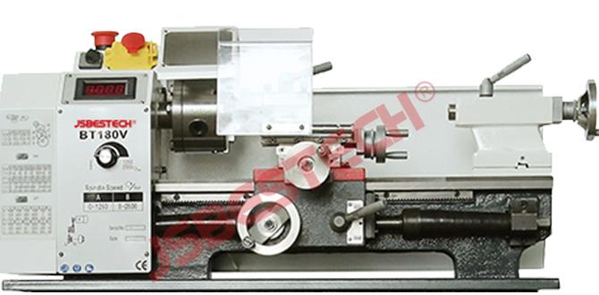
Understanding the 3/16″ Carbide End Mill for Fiberglass
Before we dive into cutting, let’s get acquainted with our star tool. A carbide end mill is designed for machining hard materials, and fiberglass is no exception. The 3/16″ size is often a sweet spot for hobbyists and DIYers, offering a good balance between detail and cutting power. When we talk about “high MRR,” it simply means this tool can remove a lot of material quickly and cleanly, which is a huge advantage when working with a material like fiberglass.
Why Carbide?
Carbide, or tungsten carbide, is an extremely hard and durable material. This hardness is crucial for cutting fiberglass because it resists the abrasive nature of the material, meaning the tool stays sharper for longer. High-speed steel (HSS) tools can work, but they’ll dull much faster when encountering fiberglass, leading to poor cut quality and requiring frequent sharpening or replacement. Carbide tooling, especially when designed for composites, offers superior performance and longevity.
What Makes a 3/16″ End Mill Great for Fiberglass?
The 3/16″ diameter is small enough for detailed work but substantial enough to handle decent depths of cut. For fiberglass machining, you’ll often find end mills with specific flute designs optimized for chip evacuation. These designs help prevent the fiberglass dust and chips from clogging the flutes, which can lead to overheating and tool damage. A dedicated fiberglass end mill will typically have polished flutes and potentially a sharp cutting edge geometry designed to shear the composite fibers cleanly.
When searching for the right end mill, you might see terms like “high MRR” or specific flute counts. For fiberglass, a 2-flute or 3-flute end mill is often recommended. More flutes can sometimes lead to chip packing in gummy materials, but with proper speeds and feeds, and good chip evacuation, they can also be very effective. Two-flute tools are generally excellent for side milling and plunging into composites, while three-flute can offer a slightly better finish in some cases.
You’ll also want to consider the “long reach” aspect if your project requires deeper cuts. A long-reach end mill has a longer flute length, allowing it to cut into deeper recesses or through thicker materials without the spindle colliding with your workpiece. Always ensure you have enough flute engagement for the desired cut depth.
Essential Considerations Before You Start
Safety and preparation are paramount. Don’t just grab the end mill and start cutting. A little forethought goes a long way in ensuring success and preventing accidents.
Safety First!
- Eye Protection: Always wear safety glasses or a full face shield. Fiberglass dust is incredibly irritating and can cause serious eye injury.
- Respiratory Protection: Fiberglass dust is a known respiratory irritant and potential carcinogen. Wear a high-quality dust mask or respirator rated for fine particulates. A shop vac with a HEPA filter is also essential.
- Hearing Protection: Machining can be noisy, so earplugs or earmuffs are recommended.
- Gloves: While the dust can be irritating to the skin, avoid sticky gloves that could get caught in the spinning tool. Nitrile gloves are a good option for protecting against dust.
- Dust Collection: This is perhaps the MOST important safety and cleanliness measure. A dust collection system connected directly to your milling machine or CNC router, with a vacuum running near the cutting point, will dramatically reduce airborne dust and keep your machine clean.
Machine Setup
Whether you’re using a manual milling machine or a CNC router, proper setup is key.
- Secure Workpiece: Ensure your fiberglass sheet or part is clamped down firmly to prevent any movement during machining. Vibration or shifting can lead to poor cuts or tool breakage.
- Rigidity: A rigid setup minimizes chatter, which is vibrations that can ruin your finish and damage your tool.
- Coolant/Lubrication: For fiberglass, dry machining is often preferred to avoid creating messy, sticky resin. If needed, a light mist of compressed air can help clear chips and cool the area. Some specialized composite machining fluids exist, but for hobbyist use, dry machining with effective dust collection is common.
Tool Selection Details
We’ve focused on the 3/16″ carbide end mill, but let’s refine the selection:
- Material: Solid carbide is preferred over carbide-tipped for its strength and wear resistance in longer, thinner tools like 3/16″ end mills.
- Flute Count: For general fiberglass cutting, 2 or 3 flutes are standard. 2-flute tools often provide better chip clearance.
- Coating: While not strictly necessary for fiberglass, some coatings can improve performance and tool life. Uncoated carbide designed for composites is often sufficient.
- Helix Angle: A standard helix angle (around 30-45 degrees) works well, but specific “composite” end mills might have optimized angles for shear strength and chip evacuation.
- Shank: Ensure the shank diameter is compatible with your milling machine’s collet system. A 1/4″ shank is common for 3/16″ end mills and often used in smaller routers and mills.
Step-by-Step Guide: Machining Fiberglass with a 3/16″ Carbide End Mill
Now, let’s get to the exciting part – making chips! This guide assumes you’re using a milling machine or a CNC router. The principles are the same.
Step 1: Prepare Your Work Area and Machine
Ensure all safety equipment is donned and dust collection is activated. Clamp your fiberglass securely to the machine bed. Double-check that there’s nothing obstructing the path of the end mill.
Step 2: Set Up Your Tool and Z-Axis
Insert the 3/16″ carbide end mill into the collet of your milling machine or router spindle. Tighten it securely. Next, you need to set your Z-axis zero point. This is typically done by touching the tip of the end mill to the top surface of your material. For CNC machines, you’ll use aității probe or manually jog the Z-axis until the end mill just kisses the surface.
Step 3: Determine Your Speeds and Feeds
This is critical for good results and tool longevity. For fiberglass, you generally want to spin the tool relatively fast, but feed it at a rate that allows the cutting edges to shear the material cleanly, not rub or melt it. Since fiberglass varies, these are starting points, and you’ll likely need to adjust.
Here’s a general guideline for a 3/16″ solid carbide end mill in fiberglass. These values are for a 2-flute end mill. For a 3-flute, you might increase the feed rate slightly while keeping RPM similar.
| Parameter | Typical Range (3/16″ Carbide) | Notes |
|---|---|---|
| Spindle Speed (RPM) | 15,000 – 25,000 RPM | Higher RPMs are generally good for composites. |
| Feed Rate (IPM – Inches Per Minute) | 15 – 40 IPM | Adjust to achieve a clean chip. Too slow causes melting, too fast can snap the tool. |
| Depth of Cut (DOC) | 0.010″ – 0.050″ per pass | Start shallow, especially on the first pass. |
| Stepover (Percentage of Tool Diameter) | 20% – 50% for profiling/contouring | Smaller stepover for smoother finish, larger for faster roughing. |
Important: The Material Removal Rate (MRR) is calculated as: ( text{MRR} = text{Width of Cut} times text{Depth of Cut} times text{Feed Rate} ). Higher MRR means faster cutting. The values above aim for a high MRR while maintaining cut quality. You can find more detailed recommendations from tool manufacturers. For instance, some specialized composite end mills from manufacturers like Harvey Tool provide specific machining parameters.
Step 4: Perform a Test Cut
Before cutting your final part, it’s highly recommended to make a test cut on a scrap piece of the same fiberglass material. This allows you to:
- Verify your speeds and feeds.
- Check the tool’s engagement and listen for unusual noises (like chattering).
- Assess the cut quality – are you getting clean edges, or is there melting/fraying?
- Confirm your dust collection is working effectively.
If the cut is rough, melt is appearing, or the tool seems to be struggling, adjust either the feed rate (increase to cut faster) or the RPM (sometimes decreasing slightly can prevent melting if the feed is too slow). Keep the depth of cut conservative.
Step 5: Execute Your Cut
Once you’re confident with your test cut, you can proceed with your actual project. For manual milling, control the feed rate smoothly. For CNC, ensure your CAM software is programmed with appropriate speeds, feeds, and cutting strategies.
Plunging: When starting a cut that goes straight down into the material (plunging), do so at a slower feed rate than your conventional milling feed rate. This reduces the risk of the tool digging in too aggressively and breaking. A typical plunge rate might be 50% of your main feed rate.
Contouring/Profiling: For cutting out shapes, use a climb milling strategy if possible (where the cutter rotates in the same direction as it’s moving into the material). This generally provides a cleaner cut and puts less stress on the tool. Ensure your CAM software is set up for this, or if manual, engage the feed in the correct direction.
Step 6: Chip Evacuation and Cooling
Keep an eye on chip formation. If you see chips building up, especially if they start to look melted or gummy, you may need to:
- Increase your feed rate slightly.
- Decrease your depth of cut.
- Ensure dust collection is at maximum efficiency.
- Use a blast of compressed air to clear chips, if safe and appropriate for your setup.
Step 7: Finishing the Cut
As the end mill approaches the end of its path, especially on pocketing operations, the chip load can change. Be prepared for this. For profile cuts, the final pass should ideally be taken at a shallow depth of cut (e.g., 0.005″ – 0.010″) with a relatively high feed rate to achieve a very smooth outer edge. This is sometimes called a “finishing pass” or “spring pass” in CNC machining.
Optimizing for High MRR in Fiberglass
High Material Removal Rate (MRR) isn’t just about cutting fast; it’s about cutting efficiently. This means removing material quickly without sacrificing quality or damaging your tool. Here’s how to maximize MRR when using your 3/16″ carbide end mill:
- Maximize Depth of Cut (DOC): While it’s important to start shallow, as you gain confidence and confirm stability, you can increasingly use the full flute length of the end mill if the rigidity of your machine and workpiece allows. This removes more material per pass of the machine.
- Increase Feed Rate: Once your DOC is set, the feed rate is the next primary lever for MRR. A good chip formation is your guide. If you’re getting clean, powdery chips or fine strands, push the feed rate a bit higher.
- Minimize Air Time: For CNC, program efficient toolpaths that reduce rapid travel moves. For manual operation, ensure your feed is consistent.
- Optimal Stepover: For roughing operations (like clearing out a large pocket), a larger stepover (up to 50% of the tool diameter) will remove material faster. For finishing passes, you’ll use a much smaller stepover.
Consider the material itself. Different types of fiberglass, like G10 or FR-4 (common for PCBs), have varying resin content and fiber density, which can affect machining. Always refer to material datasheets if available, or perform thorough testing. For a professional resource on machining composites, the CompositesWorld website offers a wealth of industry knowledge and best practices.
Common Issues and How to Solve Them
Even with the best tools, problems can arise. Here are some common issues and their solutions:
Issue: Melting or Gumming
Cause: The tool is rubbing rather than cutting, or the feed rate is too slow for the spindle speed. This generates excessive heat. Poor chip evacuation also contributes.
Solution:
- Increase the feed rate.
- Decrease the depth of cut.
- Ensure dust collection is optimal to remove chips.
- If using a CNC, check your G-code for slow feed rates.
Issue: Chattering or Vibration
Cause: The workpiece or tool is not held rigidly, the cutting tool is too long for the diameter, or the speeds/feeds are causing resonance.
Solution:
- Improve fixturing for the workpiece.
- Use a shorter tool if the cut allows, or a tool with a more rigid shank.
- Reduce depth of cut and try adjusting speeds and feeds systematically.
- Ensure your machine’s spindle bearings are in good condition.
Issue: Frayed or Delaminated Edges
Cause: The cutting edges are dull, or the feed rate is too fast for the spindle speed causing the fibers to tear rather than shear. Also, a large stepover can sometimes cause delamination.
Solution:
- Sharpen or replace the end mill.
- Slightly reduce the feed rate or ensure it’s not excessively high.
- Perform a lighter finishing pass with a finer stepover and potentially higher feed rate relative to its depth of cut.
- Ensure you are using a tool designed for composites.
Issue: Tool Breakage
Cause: Plunging too fast, sudden resistance due to poor fixturing, excessive side load, or operating at incorrect speeds/feeds leading to chipping of the carbide. Forcing the cut through a hard spot or too deep might also cause it.
Solution:
- Always plunge at a slower rate.
- Ensure the workpiece is securely clamped.
- Avoid taking excessively deep cuts or cuts that are too wide.
- Use appropriate speeds and feeds.
- Make sure the tool is centered in the collet and properly tightened.
Alternative Tools and When to Use Them
While the 3/16″ carbide end mill is excellent, other tools might be better suited for specific tasks or materials.
- Diamond-Coated/Impregnated Tools: For extremely hard composites or when tool life is paramount, these can outperform carbide. However, they are typically more expensive and generate a lot of fine dust.
- Downcut or Upcut Flutes: Standard end mills have spiral flutes. Upcut flutes pull chips up, while downcut flutes push them down. For fiberglass, straight flute or specialized composite cutters are often preferred for chip evacuation.
- Larger Diameter End Mills: For faster material removal on large, flat areas or when edge finish isn’t as critical, a 1/4″ or larger end mill can be used.
- Router Bits for Composites: For CNC routers, specific bits designed for composite materials (often with compression or V-groove designs) can yield excellent results, especially for surface finishing.
Material Properties of Fiberglass
Understanding the material you’re cutting is key:
- Abrasive Nature: Fiberglass is made of glass fibers embedded in a resin matrix