Have you ever wondered how to turn a simple piece of metal into something amazing? Using a metal lathe can do just that. But how do you get started? That’s where CAD design comes in. It makes everything easier and more precise.
Imagine you’re building a toy car. You wouldn’t just guess where to put the wheels, right? You’d want to plan it out first. Well, CAD design helps you take that first step before you start working on the lathe. It’s like drawing your dream project on paper before creating it.
Did you know that many makers use CAD to create fantastic designs? It allows them to see how their project will turn out. They can tweak anything they want before touching any tools. This way, using a metal lathe becomes even more fun and rewarding.
In this article, we will explore how to use metal lathe CAD design step by step. Soon, you’ll be ready to unleash your creativity and make cool projects come to life!
How To Use Metal Lathe Cad Design For Precision Engineering

How to Use Metal Lathe CAD Design
Using a metal lathe with CAD design can be exciting and rewarding! First, learn the basics of CAD software like setting up your workspace. Then, create a simple design, and adjust measurements for your metal piece. Did you know that accurate designs can save you time and materials? After designing, simulate the machining process before starting the lathe. This technique helps avoid mistakes and inspires confidence in your project. Explore the world of precision with your metal lathe!Understanding Metal Lathe Basics
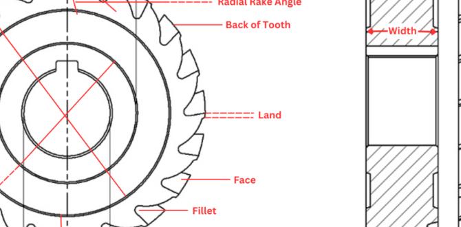
Definition and function of a metal lathe. Key components of a metal lathe.A metal lathe is like a magic wand for shaping metal. It spins the metal while cutting tools carve it into different shapes. This tool is essential in many workshops, helping create parts for machines and more. Key parts of a metal lathe include the bed, which is the sturdy base, and the headstock, where the spinning happens. Don’t forget the tailstock, which holds the other end of the metal. It’s like having a buddy to help you out!
| Key Components | Function |
|---|---|
| Bed | Sturdy base that supports all parts |
| Headstock | Houses the motor and holds the spinning workpiece |
| Tailstock | Supports the other end of the workpiece |
The Role of CAD in Metal Lathe Design
Benefits of using CAD software for lathe design. Comparison of popular CAD software options.Using CAD software for metal lathe design makes the process easier and more accurate. It allows for precise measurements and quick adjustments. With CAD, you can create 3D models, which help in visualizing the final product. Popular options include:
- AutoCAD: Great for detailed designs.
- Fusion 360: Good for collaboration and cloud storage.
- SolidWorks: Excellent for complex shapes and assemblies.
This software saves time and improves quality, giving designers an edge in their projects.
What are the benefits of CAD in lathe design?
Benefits of CAD include better accuracy, faster revisions, and improved collaboration. It makes creating and sharing designs simple.
Steps for Creating a Metal Lathe Design in CAD
Preparing initial sketches and measurements. Setting up the CAD environment and parameters.Start by drawing your ideas on paper. This helps you see what your design will look like. Measure everything carefully—it’s like measuring for new shoes. You don’t want them too tight! Next, set up your CAD software. Make sure all the settings are just right. It’s like tuning a guitar before a concert. A little adjustment makes a big difference!
| Step | Description |
|---|---|
| 1 | Initial sketches |
| 2 | Measurements |
| 3 | Set up CAD |
Remember, a good design starts with clear ideas! Let’s make some cool stuff with that metal lathe!
Designing Machinable Parts
Considerations for part geometry and tolerances. Utilizing CAD tools for precise design features.Creating parts is fun when you plan well! First, think about part geometry. This means how your piece will look and fit with others. Aim for clear shapes that will work together. Next, consider tolerances. This is about how closely parts should match. Exact fits keep everything working smoothly.
Using CAD tools helps a lot. They let you add details and check measurements easily. You can zoom in to see small features, too. Make sure to use these tools for the best results.
What are the key points to remember when designing machinable parts?
- Think about shapes and sizes – Plan the design carefully.
- Check fits – Make sure parts fit well together.
- Use CAD tools – They offer precision and clarity.
Did you know that using CAD software can save time? Many workplaces report improvements in their design efficiency by up to 30%. The right design leads to smooth production and less waste!
Exporting and Preparing Designs for Machining
Format requirements for lathe machining. Generating Gcode and other necessary files.Preparing your designs for machining is like packing for a vacation. You need the right tools and information. First, make sure your design files meet the format requirements for lathe machining. Common formats are DXF and STEP, which help your design shine like a star in the machining world.
Next, it’s time to generate Gcode and other necessary files. Gcode is like a secret language that tells the lathe what to do. Remember, a smooth operation equals a happy lathe and a pretty design!
To help you, here’s a quick look at essential file formats:
| File Type | Use |
|---|---|
| DXF | Vector drawing files for precise designs. |
| STEP | 3D design files for complex shapes. |
| Gcode | Commands for the machine to follow. |
So, remember these tips as you dive into the exciting world of metal lathe CAD design!
Common Mistakes to Avoid in CAD Metal Lathe Design
Overlooking critical dimensions and tolerances. Ignoring material properties and machining capabilities.Many new designers make silly blunders in CAD metal lathe design. One big mistake is overlooking critical dimensions and tolerances. Forgetting these can lead to parts that don’t fit together—yikes! Another common blunder is ignoring material properties and machining capabilities. Not every material behaves the same way. Some might bend like a wet noodle if you’re not careful! Check your specs twice, and always know your materials. Trust us; you don’t want your project to end up looking like a potato on a stick!
| Common Mistakes | Consequences |
|---|---|
| Overlooking critical dimensions | Parts won’t fit correctly |
| Ignoring material properties | Unexpected bending or breaking |
Tips for Optimizing Your Metal Lathe Designs
Best practices for streamlined workflows. Leveraging CAD features for efficiency and accuracy.To create great metal lathe designs, follow some simple tips. First, plan your work. This helps you stay organized. Use CAD tools to check your designs. CAD can show you errors quickly. This saves time. Also, consider these methods:
- Use templates for common shapes.
- Group similar tasks together.
- Test designs with virtual models.
This makes sure you stay on track with your project while maintaining quality.
What are the benefits of CAD in metal lathe design?
CAD improves speed and precision. It helps you visualize and adjust designs easily. This leads to fewer mistakes and better results.
Case Studies: Successful Metal Lathe Projects Using CAD
Examples from industry experts and hobbyists. Analysis of design challenges and solutions.Metal lathe projects can be quite fun! Many experts and hobbyists share cool success stories. For example, one enthusiast created a vintage car part using CAD design. The challenge was getting the curves just right. A neat design tweak made the process smoother. Professionals often face issues too, like matching precise dimensions. Yet, with CAD tools, they overcome these hurdles effectively. Here’s a quick look at some projects:
| Project | Challenge | Solution |
|---|---|---|
| Vintage Car Part | Curves matching | Design tweak |
| Bike Frame | Dimension accuracy | Punching templates |
These examples show how creativity and smart tools go hand in hand. If you think CAD is dull, think again—it’s like magic for makers!
Resources for Further Learning
Recommended books, online courses, and tutorials. Communities and forums for CAD and metalworking enthusiasts.Learning about metal lathes and CAD design can be a fun adventure! To get started, check out some amazing resources. Books like “Metalworking For Dummies” can be a great friend. Online courses on platforms like Udemy offer clear lessons. YouTube is also filled with helpful tutorials. Don’t forget to join communities and forums where fellow enthusiasts share tips. Remember, even the best inventors started with a good book and a dream!
| Resource Type | Recommended Resources |
|---|---|
| Books | “Metalworking For Dummies” |
| Online Courses | Udemy: CAD Basics |
| Tutorials | YouTube Channels on Metalworking |
| Communities | Reddit & CAD forums |
Conclusion
In summary, using CAD design for a metal lathe helps you create precise models. Start by learning basic CAD software tools. Practice designing simple parts to build your skills. Remember to plan your projects carefully and take measurements accurately. For more tips and tutorials, check out online resources. With practice, you’ll master metal lathe design in no time!FAQs
What Are The Key Features To Consider When Designing A Cad Model For Machining On A Metal Lathe?When designing a CAD model for a metal lathe, you should think about several important features. First, make sure the shape is simple and has clear edges. Second, consider the size; it should fit the lathe’s working space. You also need to choose the right materials for the part you want to make. Finally, think about how to hold the piece in place while it is being made.
How Can I Effectively Translate My Cad Design Into G-Code For Use With A Cnc Metal Lathe?To turn your computer design into G-code for a CNC (Computer Numerical Control) metal lathe, first, use software that can do this. Many programs, like Fusion 360 or SolidWorks, help you convert your designs into G-code. After that, check the code for any mistakes. Lastly, load the G-code into your CNC machine and run it to make your metal part.
What Software Options Are Available For Creating Cad Designs Specifically Optimized For Metal Lathe Machining?You can use different software to create designs for metal lathes. Some popular options are Autodesk Fusion 360, SolidWorks, and TinkerCAD. These programs help you make detailed 3D models. They are user-friendly and great for beginners. You can choose one based on your needs and experience level.
How Do I Ensure That My Cad Design Accounts For Tooling Geometry And Machining Tolerances On A Metal Lathe?To make sure your CAD design works well with a metal lathe, you should first understand the shapes tools can take. Look at how thick or thin parts need to be. Always leave a little extra space for changes during the cutting process. Check the measurements carefully before starting. You can also ask someone with experience for advice.
What Common Mistakes Should I Avoid When Preparing A Cad Model For A Metal Lathe To Ensure Efficient Machining?When you prepare a CAD model for a metal lathe, avoid these mistakes. First, make sure your measurements are correct. If they are wrong, the pieces won’t fit. Next, don’t forget to add enough space for tools to move. Also, check that all parts are designed for the right material. Lastly, keep your design simple to help the lathe work better.
{“@context”:”https://schema.org”,”@type”: “FAQPage”,”mainEntity”:[{“@type”: “Question”,”name”: “What Are The Key Features To Consider When Designing A Cad Model For Machining On A Metal Lathe? “,”acceptedAnswer”: {“@type”: “Answer”,”text”: “When designing a CAD model for a metal lathe, you should think about several important features. First, make sure the shape is simple and has clear edges. Second, consider the size; it should fit the lathe’s working space. You also need to choose the right materials for the part you want to make. Finally, think about how to hold the piece in place while it is being made.”}},{“@type”: “Question”,”name”: “How Can I Effectively Translate My Cad Design Into G-Code For Use With A Cnc Metal Lathe? “,”acceptedAnswer”: {“@type”: “Answer”,”text”: “To turn your computer design into G-code for a CNC (Computer Numerical Control) metal lathe, first, use software that can do this. Many programs, like Fusion 360 or SolidWorks, help you convert your designs into G-code. After that, check the code for any mistakes. Lastly, load the G-code into your CNC machine and run it to make your metal part.”}},{“@type”: “Question”,”name”: “What Software Options Are Available For Creating Cad Designs Specifically Optimized For Metal Lathe Machining? “,”acceptedAnswer”: {“@type”: “Answer”,”text”: “You can use different software to create designs for metal lathes. Some popular options are Autodesk Fusion 360, SolidWorks, and TinkerCAD. These programs help you make detailed 3D models. They are user-friendly and great for beginners. You can choose one based on your needs and experience level.”}},{“@type”: “Question”,”name”: “How Do I Ensure That My Cad Design Accounts For Tooling Geometry And Machining Tolerances On A Metal Lathe? “,”acceptedAnswer”: {“@type”: “Answer”,”text”: “To make sure your CAD design works well with a metal lathe, you should first understand the shapes tools can take. Look at how thick or thin parts need to be. Always leave a little extra space for changes during the cutting process. Check the measurements carefully before starting. You can also ask someone with experience for advice.”}},{“@type”: “Question”,”name”: “What Common Mistakes Should I Avoid When Preparing A Cad Model For A Metal Lathe To Ensure Efficient Machining? “,”acceptedAnswer”: {“@type”: “Answer”,”text”: “When you prepare a CAD model for a metal lathe, avoid these mistakes. First, make sure your measurements are correct. If they are wrong, the pieces won’t fit. Next, don’t forget to add enough space for tools to move. Also, check that all parts are designed for the right material. Lastly, keep your design simple to help the lathe work better.”}}]}