Tialn Ball Nose End Mill: The Secret to Fast Aluminum Cuts!
Tired of slow, jerky aluminum milling? A TiAlN ball nose end mill, especially one with a 40-degree helix angle, is your key to unlocking proven speed and smooth finishes on aluminum 6061 for roughing and beyond. This guide breaks down how to use it effectively for quicker, cleaner results.
Milling aluminum can sometimes feel like fighting the material. Chips get sticky, tools wear down fast, and your progress seems to crawl. It’s a common frustration for many in the home shop. But what if there was a way to make those aluminum cuts fly by, leaving a beautiful finish behind? There is, and it often starts with the right tool and coating. We’re going to dive into how a TiAlN ball nose end mill can dramatically improve your aluminum machining. You’ll learn what makes it special and how to use it to speed up your work. Get ready to cut aluminum faster and better than you ever thought possible!
Why TiAlN for Aluminum? Understanding the Magic
Aluminum is a fantastic material to work with – it’s lightweight, strong, and relatively easy to machine. However, it has a tendency to be “gummy.” This means it can stick to the cutting edges of your end mill, causing poor chip formation, increased friction, and premature tool wear. This is where specialized coatings on your end mill come into play.
The Power of Titanium Aluminum Nitride (TiAlN)
TiAlN is a mouthful, but it’s your best friend when it comes to machining aluminum. Here’s why:
Heat Resistance: TiAlN coatings are known for their excellent thermal stability. While dedicated aluminum end mills often have coatings designed for lower friction, TiAlN offers a great balance. It forms a protective, hard oxide layer at very high temperatures. This oxide layer prevents the aluminum from welding onto the cutting edge.
Hardness: The coating itself is incredibly hard, which helps it resist wear and maintain its sharp cutting edge for longer, especially important when dealing with the abrasive nature of some aluminum alloys.
Lubricity (Indirectly): While not as slippery as some specialized aluminum coatings, the hard, smooth surface of TiAlN helps reduce friction compared to an uncoated end mill. Less friction means less heat buildup and better chip evacuation.
Versatility: While we’re focusing on aluminum, TiAlN is remarkably versatile and can handle other materials too, making it a valuable addition to any machinist’s toolkit.
The Ball Nose Advantage
A ball nose end mill has a hemispherical tip. This shape is perfect for a variety of tasks:
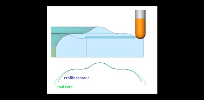
3D Contouring and Sculpting: Its rounded tip allows for smooth, flowing surface finishes in complex shapes, like carving a mold or creating detailed model parts.
Slotting: While not ideal for deep, narrow slots, it can mill wider slots or the bottom of pockets with a rounded profile.
Roughing and Finishing: The shape allows for aggressive material removal during roughing passes. For finishing, it can create perfectly radiused corners and blended surfaces.
When you combine the TiAlN coating with a ball nose geometry, you get a tool that’s exceptionally well-suited for tackling aluminum efficiently. The coating manages heat and wear, while the ball nose geometry allows for versatile machining paths, including those that embrace the material’s tendency to deform.
Choosing Your TiAlN Ball Nose End Mill for Aluminum
Not all TiAlN ball nose end mills are created equal, especially when it comes to machining aluminum. Several factors are crucial for optimal performance.
Material: Specifically 6061 Aluminum
6061 aluminum is one of the most common alloys used by hobbyists and in manufacturing. It’s a great choice for its strength-to-weight ratio and corrosion resistance. However, as mentioned, it can be gummy. Your tool choice needs to account for this.
Helix Angle: The Secret Sauce (Often 40 Degrees)
The helix angle refers to the angle of the flutes (the spiral grooves) around the tool. For aluminum, a higher helix angle (typically 30-50 degrees) is generally preferred.
Higher Helix Angle (e.g., 40 Degrees):
Improved Chip Evacuation: The steeper spiral helps “throw” chips away from the cutting zone more effectively. This is critical for aluminum, as it prevents chips from re-cutting and causing poor surface finishes or tool breakage.
Shear Cutting Action: A higher helix angle provides a higher shear angle. This means the cutting edge slices through the material more cleanly, generating less heat and reducing the tendency for aluminum to stick.
Smoother Finish: This cleaner cut often results in a superior surface finish.
While a 30-degree helix is also common and works well, a 40-degree helix angle on a TiAlN ball nose end mill is often considered the sweet spot for aggressive and smooth aluminum machining, offering a proven speed advantage.
Number of Flutes
For aluminum, a general rule of thumb is to use end mills with fewer flutes.
2 or 3 Flutes: These are excellent for aluminum. They provide more chip room between the flutes, which is essential for managing sticky chips. They also allow for higher feed rates.
4 Flutes: While 4-flute end mills are great for harder materials and finishing, they can sometimes pack up with chips in softer materials like aluminum. If using a 4-flute for aluminum, you’ll need very aggressive chip evacuation strategies (like high-pressure coolant or air blast) and careful feed rate management.
For roughing and achieving speed in aluminum 6061, a 2-flute TiAlN ball nose end mill with a 40-degree helix angle is a superb choice.
Flute Configuration: Single Flute vs. Multi-Flute
Single Flute: Ideal for very gummy materials like aluminum, plastics, and copper. They offer maximum chip clearance and allow for very high feed rates. However, they can be less rigid and might vibrate more easily.
Two Flutes: A great workhorse for aluminum. They provide good chip clearance and stability.
Three/Four Flutes: Better for harder materials or finishing passes where chip clearance is less of a concern and rigidity is prioritized.
Setting Up Your Machine for Success
The tool is only part of the equation. Your machine setup and parameters are just as important for unlocking the full potential of your TiAlN ball nose end mill in aluminum.
Workholding is Key
A secure workholding setup is non-negotiable. Aluminum can exert significant forces during machining.
Proper Clamping: Ensure your workpiece is firmly clamped to prevent any movement. Use appropriate vises, clamps, or fixtures.
Avoid Vibration: Any looseness in your setup will lead to vibration, which degrades finish quality and can break tools.
Coolant and Lubrication: Essential for Aluminum
While TiAlN provides heat resistance, actively managing heat and lubrication is crucial for cutting aluminum smoothly.
Cutting Fluid: Using a suitable cutting fluid or lubricant is vital. It cools the cutting zone, lubricates the interface between the tool and workpiece, and helps to wash chips away. Look for fluids specifically formulated for aluminum or general-purpose high-performance coolants. A flood coolant system is ideal, but mist coolant or even a good spray can make a difference.
Flood Coolant: Provides the best cooling and chip flushing.
Mist Coolant: A good compromise for many home shops, offering cooling and lubrication without the mess of flood coolant.
Air Blast: Can help clear chips, especially in combination with a lubricant.
The Society of Manufacturing Engineers (SME) offers extensive resources on machining practices, including the importance of coolant for different materials. You can explore their publications for deeper insights into optimal cutting conditions.
Spindle Speed (RPM) and Feed Rate (IPM/mm/min)
This is where you harness that “proven speed.” Finding the right balance of spindle speed and feed rate (the speed at which the tool moves through the material) is critical. These settings depend on several factors:
End Mill Diameter: Larger diameters generally require lower RPMs and higher feed rates.
Machine Rigidity: A solid, powerful machine can handle higher speeds and feeds.
Depth of Cut (DOC): How deep you’re cutting into the material. Shallower cuts allow for faster speeds and feeds.
Width of Cut (WOC): How wide your cut is.
General Starting Points for 6061 Aluminum with a TiAlN Ball Nose End Mill (e.g., 1/2 inch diameter, 2-flute):
Spindle Speed (RPM): Often in the range of 5,000 – 15,000 RPM. Start conservatively and listen to the cut. A high-pitched squeal often indicates you’re too fast (or not enough lubrication), while a loud chattering suggests you’re too slow or the feed rate is too high for the depth/width of cut.
Feed Rate (IPM – Inches Per Minute / mm/min): This is where you can gain speed. Aim for a feed rate that allows the tool to “slice” the aluminum rather than “rub” it. For a 1/2″ end mill, this could be anywhere from 20-80 IPM or even higher, depending on your DOC/WOC.
Depth of Cut (DOC): For roughing, you might aim for 0.1 – 0.5 times the tool diameter. For finishing, use very shallow DOCs (e.g., 0.005″ – 0.015″).
Always consult the end mill manufacturer’s recommendations! They usually provide starting parameters for specific materials. If you can’t find them, start conservatively and increase slowly.
Chip Load
Chip load is the thickness of the material removed by each cutting edge per revolution. Understanding chip load helps you dial in your feed rate and RPM.
Chip Load Formula: Chip Load = Feed Rate / (RPM Number of Flutes)
Goal for Aluminum: You want chips that are about the size of a fingernail clipping – not powder (too little material being removed) and not long, stringy, gummy chips (too much material).
For aluminum, a chip load around 0.003″ to 0.010″ per tooth is a common target, depending on the tool diameter.
Step-by-Step: Milling Aluminum with Your TiAlN Ball Nose End Mill
Let’s walk through the process. We’ll assume you’re using a CNC mill, but many principles apply to manual milling too.
Step 1: Job Setup and Fixturing
Secure the Workpiece: Mount your 6061 aluminum stock firmly in your vise or fixture. Ensure it’s seated properly and won’t move during the operation.
Tool Selection and Installation: Insert your TiAlN ball nose end mill into the collet or tool holder. Ensure it’s clean and properly seated to avoid runout (wobble).
Machine Preparation: Ensure your coolant system is ready, or you have your lubrication method planned.
Step 2: Setting Work Coordinate System (WCS) and Tool Length Offset
Zeroing the Machine: Set your X, Y, and Z origin points on your workpiece. The Z-axis zero is typically set at the top surface of your material.
Tool Length Offset: Measure and input the accurate length of your end mill into the machine’s control. This is critical for accurate cutting depths.
Step 3: Program Generation (CAM) or Manual Programming
CAM Software: If using CAM software (like Fusion 360, Mastercam, etc.), you’ll typically select a 3D contour or adaptive clearing strategy. Input your tool parameters (diameter, flutes, helix angle, coating), material (aluminum 6061), and desired cutting parameters (stepover, stepdown, feed rate, spindle speed). The software will generate the toolpath.
Manual Programming (G-code): For simpler shapes, you might write G-code directly. This involves defining the toolpath movements (G01 for linear, G02/G03 for arcs), feeds, and speeds. You’ll likely use G54 for your work offset and M3 for spindle start, M8 for coolant.
Step 4: Initializer Passes and Verification
The goal here is to test your program and parameters without risking the tool or workpiece.
Dry Run (Air Cut): Many CNC machines have an “air cut” mode where the machine moves as if cutting but the spindle doesn’t turn or the Z-axis is set much higher. This allows you to visually check your toolpath for collisions and ensure it follows the intended geometry.
First Cut in Material:
Reduce Feed Rate: Begin with a feed rate that’s 50% of your target.
Set Depth of Cut: Start with a conservative depth of cut (e.g., 0.05″ – 0.1″ for a 1/2″ end mill).
Observe the Chips: As the tool begins to cut, carefully observe the chips being produced. Are they looking good? (Clean, chip-like, not gummy).
Listen to the Sound: The machine should sound smooth, like a clean slicing noise, not a grinding or chattering sound.
Check for Build-up: Briefly pause the machine and check if aluminum is sticking to the tool.
Step 5: Iterative Parameter Adjustment
Increase Feed Rate: If the initial cut looks good, pause the machine, and gradually increase the feed rate in increments (e.g., 10-20% at a time) until you reach your target feed rate or start to hear or see signs of stress on the tool.
Adjust Depth/Width of Cut: If you’re limited by tool deflection or chatter, you might need to reduce the depth of cut or width of cut.
Spindle Speed: While feed rate is key for speed, RPM influences chip load and surface finish. If you’re getting a poor finish, sometimes a slight RPM adjustment can smooth it out.
Coolant: If you see aluminum building up or hear excessive friction, increase coolant flow or consider a better lubricant.
Step 6: High-Speed Roughing and Finishing Passes
Once your parameters are dialed in, you can let the machine run.
Roughing: Use a relatively aggressive depth and width of cut to quickly remove bulk material. Your TiAlN ball nose end mill with a 40-degree helix is built for this.
Finishing: After roughing, use smaller stepovers (the amount the tool moves sideways for each pass – e.g., 20-40% of the tool diameter for ball nose) and very shallow depths of cut to achieve a smooth, accurate surface finish. The ball nose geometry excels here for creating blended contours.
Benefits of Using a TiAlN Ball Nose End Mill for Aluminum
Implementing this specific tool choice and approach brings several advantages:
Increased Machining Speed: This is the primary benefit. Faster feed rates mean shorter cycle times for your parts.
Improved Surface Finish: The clean slicing action and effective chip evacuation lead to smoother, more accurate surfaces, often reducing the need for secondary finishing operations.
Extended Tool Life: By effectively managing heat and preventing aluminum build-up, the TiAlN coating and proper parameters help your end mill last much longer, saving you money.
Reduced Risk of Tool Breakage: Good chip evacuation and controlled cutting forces significantly lower the chance of the tool shattering.
Greater Versatility: The ball nose shape allows for intricate 3D features, making the tool useful for a wider range of projects beyond basic pocketing.
Troubleshooting Common Issues
Even with the right tools, you might encounter some snags. Here’s how to address them:
Aluminum Sticking to the End Mill (Galling):
Cause: Insufficient lubrication, too slow spindle speed, too high feed rate for the depth of cut, or lack of effective chip evacuation.
Solution: Increase coolant/lubricant flow. Experiment with a slightly higher spindle speed or lower feed rate. Reduce depth of cut. Ensure you’re using a recommended flute count and helix angle for aluminum. Make sure your CAM strategy is focused on chip thinning.
Poor Surface Finish / Chatter:
Cause: Machine rigidity issues, loose workholding, worn tool, incorrect feed rate/RPM combination, excessive depth of cut.
Solution: Double-check workholding. Try a shallower depth of cut. Adjust feed rate and spindle speed – sometimes a slight increase in RPM can smooth out chatter. Ensure your tool isn’t worn. Consider climb milling where appropriate for a better finish.
Tool Breakage:
Cause: Aggressive feed rates when starting, insufficient chip evacuation leading to chip recutting, plunging too fast, workpiece movement.
Solution: Always start with conservative parameters and increase gradually. Ensure excellent chip clearance. Use appropriate plunging strategies (e.g., helical interpolation if possible, rather than straight Z-axis plunge). Verify workholding.
Recommended Resources for Machining Aluminum
As you delve deeper into machining aluminum, these authoritative resources can provide invaluable insights and best practices.
Machinery’s Handbook: Often called the machinist’s bible, this comprehensive reference contains tables and data for cutting speeds, feeds, material properties, and much more. You can find it through publishers like Industrial Press or major online booksellers.
Government & Standards Organizations: For official engineering standards and material specifications, look to organizations like:
* ASTM International (www.astm.org):