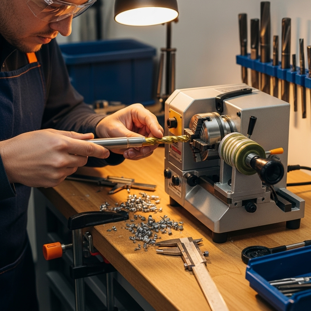
A carbide end mill, especially a 1/4 inch 1/4 shank stub length, is crucial for achieving long tool life when machining G10 composites. It offers the hardness and sharpness needed to cut G10 without excessive wear, preventing premature dulling and ensuring precise results for your projects.
Working with cool materials like G10 can be really satisfying, but it can also be tough on your tools. If you’ve ever noticed your bits wearing out too quickly when cutting G10, you’re not alone. It’s a common frustration, but the good news is there’s a simple, effective solution. Using the right tool, specifically a carbide end mill, makes a world of difference. In this guide, we’ll walk you through why carbide is the champion for G10 and how choosing the right kind will extend your tool’s life, keeping your projects on track and your wallet happier. Get ready to cut G10 with confidence!
Carbide End Mills: Your Secret Weapon for Cutting G10
G10 is an amazing material. It’s a high-pressure fiberglass laminate, meaning it’s made by stacking layers of fiberglass cloth and impregnating them with an epoxy resin. This gives it incredible strength, durability, and a smooth, flat finish, making it a favorite for knife scales, circuit boards, and various industrial parts. However, this very toughness, especially the abrasive nature of the epoxy resin binder, can be a real challenge for standard cutting tools.
When you try to machine G10 with less durable tooling, you’ll quickly run into problems. The material acts like a sandpaper, quickly dulling the cutting edges. This not only leads to a shorter tool life but also results in poor cut quality, with fuzzy edges and increased heat generation. This heat can melt the epoxy resin, creating a gummy mess that further stresses your tool and can even damage your workpiece. So, what’s the solution?
The answer lies in the material science of your cutting tools. For materials like G10, nothing beats the performance and longevity of a carbide end mill.
Why Carbide is King for G10
Carbide, specifically tungsten carbide, is a composite material formed by mixing fine powders of tungsten carbide particles with a binder, usually cobalt. This creates an exceptionally hard and dense material. Here’s why this makes it ideal for G10:
Extreme Hardness: Carbide’s hardness is significantly greater than that of High-Speed Steel (HSS) or even cobalt steels. This allows it to resist the abrasive wear from the glass fibers and epoxy in G10, keeping its sharp edge for much longer.
High-Temperature Resistance: Machining G10 generates heat. Carbide can withstand these higher temperatures without softening, which HSS tools would do. This prevents the cutting edge from deforming and losing its sharpness.
Rigidity: Carbide is a stiff material, meaning it deflects less under cutting forces. This leads to more accurate cuts and a better surface finish on G10.
Sharpness Retention: Due to its hardness and wear resistance, carbide tools hold their sharp edge for extended periods, even in abrasive materials.
Understanding End Mill Basics

Before we dive into specific carbide end mills for G10, let’s quickly cover what an end mill is and its key features. An end mill is a type of rotating cutting tool used in milling machines to create slots, profiles, pockets, and holes. They come in various shapes, sizes, and flute configurations.
Shank: This is the part of the end mill that is held by the tool holder in the milling machine. The diameter of the shank dictates the tool holder size needed.
Flutes: These are the helical grooves that run along the cutting portion of the end mill. They serve two main purposes: to create cutting edges and to evacuate chips from the cut. The number of flutes and their geometry are critical for different materials and operations.
Cutting Diameter: This is the widest part of the end mill, which determines the width of the cut it can make.
Length: End mills come in different lengths, affecting their reach and rigidity. Shorter, “stub” length end mills are generally more rigid and less prone to vibration, which is beneficial for machining harder materials.
The Ideal Carbide End Mill for G10
When selecting a carbide end mill for G10, a few specific characteristics will maximize your tool life and cutting performance.
1. Material: Solid Carbide is the Way to Go
For G10, you absolutely want a solid carbide end mill. This means the entire tool is made from tungsten carbide. Avoid end mills that have inserted carbide teeth on a steel body; these are typically for much heavier, industrial-grade machining and may not perform as well for the finer details often required with G10.
2. Flute Count: Fewer is Often Better for Composites
While end mills can have 2, 3, or 4 (or more) flutes, for G10, a 2-flute or 3-flute end mill is generally preferred. Here’s why:
2-Flute: Offers excellent chip clearance, which is vital for G10. As G10 is cut, it produces a relatively fine dust. Good chip evacuation prevents this dust from packing into the flutes, which can cause overheating and tool breakage. The larger gullet (the space between flutes) of a 2-flute end mill handles this well. They are also very good for slotting operations.
3-Flute: Provides a smoother finish than a 2-flute because the cutting edges are spaced more closely. They can also handle slightly higher feed rates in some situations. However, chip clearance can be a bit more restricted. For G10, a 3-flute is a good compromise if finish is paramount.
4-Flute (and above): Generally not recommended for G10. The chip clearance is significantly reduced, making them very prone to clogging and overheating with G10 dust.
Key takeaway: For most G10 machining, a 2-flute solid carbide end mill is your safest bet for long tool life and easy chip evacuation.
3. Type of Carbide End Mill: Uncoated vs. Coated
Carbide end mills can be uncoated or coated with various materials (like TiAlN, TiCN, or DLC).
Uncoated Solid Carbide: For G10, an uncoated end mill is often sufficient and can provide excellent results with the right machining parameters. It’s the simplest and most cost-effective option.
Diamond-Like Carbon (DLC) Coated: If you’re doing a lot of high-volume G10 machining or want the absolute best performance and wear resistance, a DLC coated end mill is a fantastic choice, though more expensive. DLC coatings are inherently hard, slick, and offer excellent abrasion resistance, which is perfect for composites like G10.
For beginner to intermediate users working on hobby projects or smaller production runs, a good quality uncoated solid carbide end mill will serve you exceptionally well.
4. Geometry: Sharp Edges and Corner Radii
Sharp Edges: Ensure the end mill has sharp cutting edges. Inspect it visually or by feel (carefully!). A dull edge will struggle and generate more heat.
Corner Radius: For G10, an end mill with a sharp, square corner is often used for general profiling and pocketing. However, if you want to reduce stress on the corners and prevent chipping, a small corner radius (e.g., 0.010″ or 0.020″) can be beneficial. For precision work where sharp internal corners are required, a square end mill is necessary.
The “Stub Length” Advantage

When we talk about specific dimensions, the concept of “stub length” becomes very important for maximizing G10 tool life, especially for smaller diameter end mills like the 1/4 inch size.
A standard end mill has a flute length that is typically 2 to 3 times its diameter. A stub length end mill has a flute length that is shorter, usually closer to 1.5 times its diameter.
Why is stub length so good for G10?
Increased Rigidity: Shorter tools are inherently more rigid. Less of the end mill is sticking out from the tool holder, which means it deflects less under cutting forces. This reduced runout and increased stability directly translate to less vibration, cleaner cuts, and a lower risk of breaking the delicate carbide tool.
Reduced Chatter: Vibration, or chatter, is a common enemy of tool life and surface finish. The stiffness of a stub length end mill helps to damp out vibrations, leading to a smoother cutting action.
Better Control: With less overhang, you have better control over the cutting process. This is especially helpful when you’re just starting out or working with precise tolerances.
So, when you’re searching for that perfect G10 end mill, look for the description “stub length” or “short flute” in addition to solid carbide and the desired diameter.
The “1/4 Inch 1/4 Shank Stub Length” Sweet Spot
This specific combination – a 1/4 inch (0.250″) diameter, 1/4 inch (0.250″) shank, and stub length – is a popular and highly effective choice for a wide range of G10 machining tasks on desktop CNC machines and small milling setups.
1/4 Inch Diameter: This size is versatile. It’s large enough to be robust but small enough to create fine details and fit into the tighter spaces often encountered when working with G10 for things like knife scales or electronic enclosures.
1/4 Inch Shank: This is a very common shank size for smaller machinery, meaning you’ll likely have suitable tool holders readily available.
Stub Length: As discussed, this provides the rigidity needed to handle the material effectively and prevent breakage.
Machining G10: Best Practices with Your Carbide End Mill
Simply having the right tool isn’t the whole story. How you use it is equally important for achieving that coveted long tool life. G10 requires a specific approach.
1. Set Up Your Machine Correctly

Rigidity is Key: Ensure your CNC machine or milling machine is as rigid as possible. Secure your workpiece firmly. Any flex in the machine or workholding will be amplified and lead to tool breakage.
Tool Holder: Use a high-quality, runout-free tool holder. A collet chuck or a precision milling chuck is far superior to a simple set-screw holder for holding small end mills. Excessive runout will cause uneven cutting and premature wear.
Spindle Speed (RPM): G10 generally prefers higher spindle speeds compared to softer materials. For a 1/4 inch carbide end mill, speeds in the range of 10,000 to 24,000 RPM are common. The exact speed will depend on your machine, the specific end mill, and your cutting parameters. Start on the lower end and increase if you’re getting a good finish and chip formation.
Feed Rate: This is the speed at which the tool advances through the material. For G10, you want a feed rate that is fast enough to allow the cutting edges to actually cut rather than rub, but slow enough to prevent chatter and excessive heat. Chip thinning can occur if your feed rate is too high for the depth of cut.
2. Chip Evacuation is Paramount
As mentioned, G10 creates dust. If this dust isn’t removed, it can re-cut, build up heat, and lead to tool failure.
Air Blast: Always use an air blast directed at the cutting zone. This helps to blow chips away and keeps the tool cool.
Peck Drilling/Clearing: For pockets or deep slots, consider using a “peck cycle” or clearing strategy in your CAM software. This involves making shallow partial depth cuts, retracting the tool to clear chips, and then continuing.
Coolant/Lubrication (Use with Caution): While some machinists use coolant, it can sometimes mix with G10 dust to form a sticky paste. A strong air blast is often sufficient and cleaner. If you do use a coolant, a flood coolant system that washes chips away effectively is best. Never use traditional cutting oil or lubricants, as they can gum up badly with G10.
3. Chip Load and Depth of Cut

Chip Load: This refers to the thickness of the chip being removed by each cutting edge. A good chip load ensures the tool is actively cutting, not rubbing. For a 1/4 inch carbide end mill in G10, target chip loads often fall in the range of 0.002″ to 0.005″ per flute.
Depth of Cut (DOC): For G10, it’s generally best to use a shallow depth of cut, especially when plunging or ramping.
Radial Depth of Cut (WOC – Width of Cut): When cutting profiles, don’t try to hog out a lot of material in one pass. For a 1/4 inch end mill, a 0.050″ to 0.100″ radial depth of cut is a good starting point. You can experiment with taking multiple passes.
Axial Depth of Cut (AOC – Axial Depth of Cut): When plunging or slotting, keep your axial depth of cut relatively conservative. For a 1/4 inch stub length end mill, an AOC of 0.100″ to 0.250″ is typical, depending on the rigidity of your setup. Always prioritize chip evacuation.
4. Machining Strategies
Climb Milling vs. Conventional Milling: For G10, climb milling is generally preferred when possible. In climb milling, the cutter rotates in the same direction as the feed. This results in a thinner chip at the start of the cut and a thicker chip at the end, leading to less heat buildup and a better surface finish. Conventional milling, where the cutter rotation is opposite to the feed, tends to push the material away and can cause more tool wear and chatter. You might need to experiment depending on your specific machine and CAM software capabilities.
Ramping: Instead of plunging straight down into G10, which puts immense stress on the end mill during the initial entry, use a ramping motion. This involves feeding the end mill into the material at an angle (e.g., 5-10 degrees). Most CAM software has a “ramp” or “helix” function for this.
Finishing Passes: For critical applications where a very smooth finish is required, consider taking a final finishing pass at a very light depth of cut (e.g., 0.005″ to 0.010″) and a slightly increased feed rate to achieve a pristine surface.
5. Tool Wear Monitoring
Even with the best practices, all tools wear out. Pay attention to the sound of the cut, the chips being produced, and the finish of the part.
Sound: A healthy cut should sound like a continuous, light “hiss” or “crumble.” If it starts to sound “screechy,” “gritty,” or “rough,” your tool is likely dulling or you have a parameter issue.
Chips: Fine, powdery dust can indicate the tool is rubbing. You want small, curly, or granular chips.
Finish: A dull tool will leave a rough, fuzzy, or melted surface.
If you notice any of these signs, it’s time to replace the end mill before it breaks. A broken carbide end mill can cause significant damage to your machine and workpiece.
Example Parameters for a 1/4″ Carbide End Mill in G10
These are starting points and will need to be adjusted based on your specific machine, material batch, and end mill.
| Parameter | Recommended Value (Approximate) | Notes |
| :—————— | :—————————— | :———————————————————————————- |
| End Mill Type | 2-Flute Uncoated Solid Carbide | Stub length, 1/4″ diameter, 1/4″ shank |
| Spindle Speed (RPM) | 15,000 – 20,000 RPM | Higher RPMs generally better, but listen to the cut. |
| Feed Rate (IPM) | 15 – 30 IPM | Start lower, listen for chatter, look at chip formation. |
| Chip Load per Flute | 0.002″ – 0.004″ | Ensure this is achieved by Feed Rate / (RPM # of Flutes). |
| Axial Depth of Cut (AOC) | 0.100″ – 0.250″ | For plunging/slotting. Conservative is better. Use ramping. |
| Radial Depth of Cut (WOC) | 0.050″ – 0.100″ | For profiling. Less is more, especially for multiple passes. |
| Ramping Angle | 5 – 10 degrees | Essential for plunge operations. |
| Cooling/Lubrication | Compressed Air Blast | Keeps chips clear and tool cool. |
Important Note on Feed Rate and RPM: The relationship between Feed Rate, RPM, and Chip Load is crucial.
Chip Load = Feed Rate / (Revolutions Per Minute Number of Flutes)
If you set a desired Chip Load, you can calculate the required Feed Rate:
Feed Rate = RPM Number of Flutes Chip Load
For example, with a 1/4″ 2-flute end mill at 18,000 RPM, aiming for a chip load of 0.003″:
Feed Rate = 18,000 RPM 2 flutes 0.003 inch/flute = 108 IPM.
You might start with a slightly lower feed rate (around 20-30 IPM for


