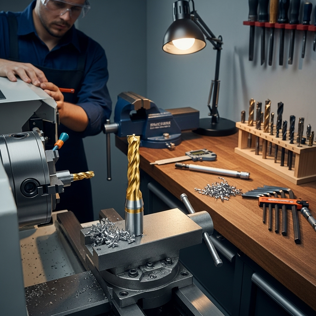
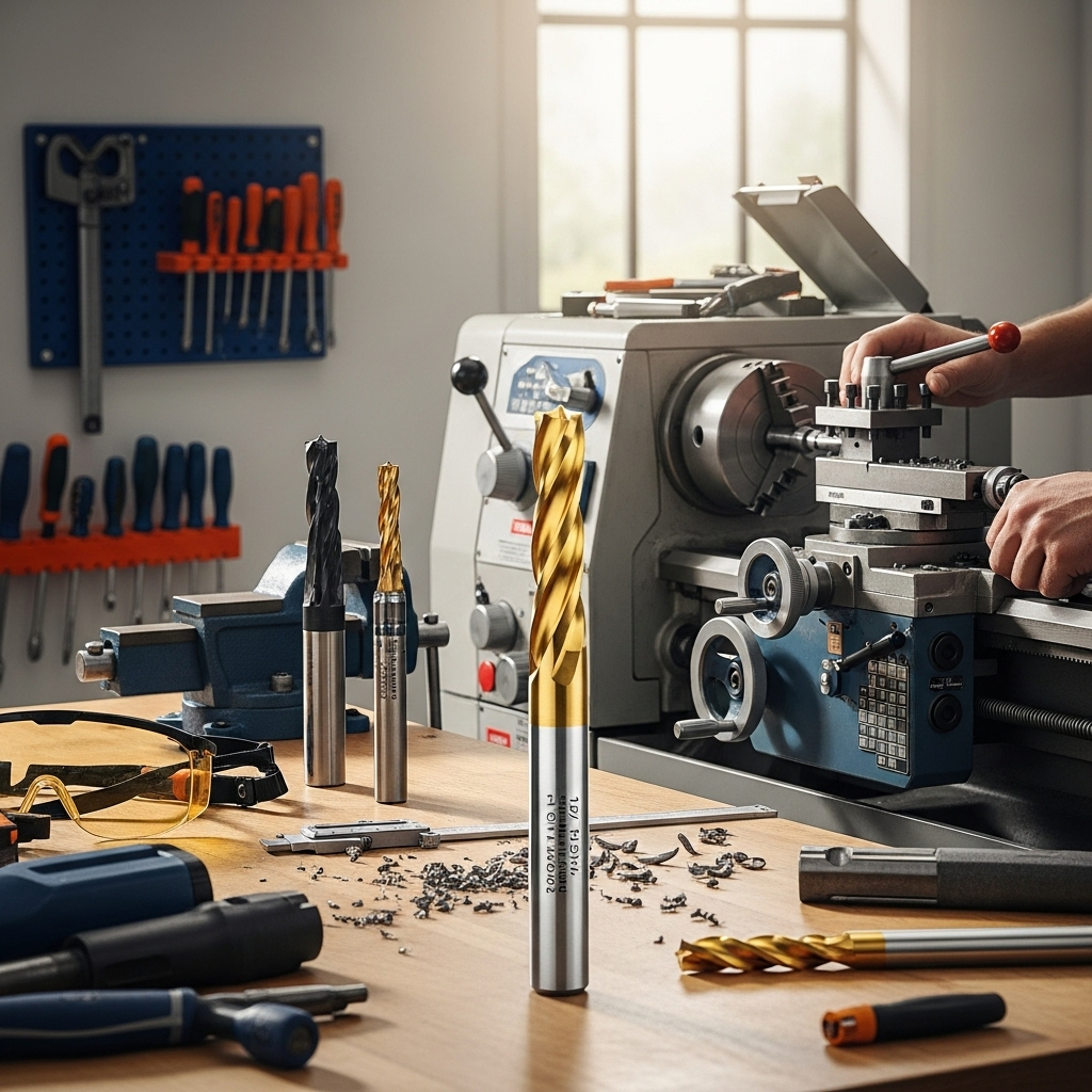
A 1/8″ carbide end mill with a 1/4″ shank and a reduced neck is a proven choice for machining D2 tool steel. This combination offers the necessary strength and precision to tackle this tough, heat-resistant material effectively.
Hey there, fellow makers and machinists! Daniel Bates here, from Lathe Hub. Ever stare at a block of D2 tool steel and feel a twinge of doubt, especially when it comes to milling? You’re not alone! This stuff is notoriously tough, and picking the wrong tool can lead to frustration, broken bits, and wasted time. But what if I told you there’s a specific combination that works like a charm for D2, even for those of us just getting started? It’s all about the right carbide end mill. In this guide, we’ll dive deep into why a 1/8-inch carbide end mill, often with a 1/4-inch shank and a reduced neck, is your secret weapon for successfully milling D2 tool steel. No more guesswork – just clear, step-by-step advice to get you cutting confidently. Let’s get started!
Why D2 Tool Steel is a Milling Challenge
D2 tool steel is a workhorse in the machining world, prized for its exceptional hardness, wear resistance, and toughness. These qualities make it fantastic for tools like dies, punches, molds, and high-quality knives. However, these same characteristics present a significant challenge when you’re trying to machine it, especially with a milling machine.
D2’s high carbon and chromium content contribute to its hardness and wear resistance. When heated during its manufacturing process, these elements form carbides within the steel’s matrix. These carbides are incredibly hard, almost like tiny ceramic particles embedded in the metal. When a cutting tool encounters these carbides, it experiences immense stress and friction. Ordinary high-speed steel (HSS) end mills can quickly dull or even chip when trying to cut D2, especially if the steel is hardened.
Furthermore, D2’s toughness means it has a high tensile strength. It wants to resist deformation. This can lead to the material “galling” or ‘sticking’ to the cutting edge of your end mill, especially at slower speeds or with insufficient lubrication. This galling can tear out chunks of the tool or the workpiece, leading to a poor surface finish and potentially catastrophic tool failure.
Given these properties, selecting the right cutting tool is paramount. You need something that can withstand extreme hardness, resist wear, and manage the heat generated during the cutting process without compromising the integrity of the workpiece or the tool itself. This is where specialized tooling, like the carbide end mill we’re focusing on, comes into play.
The Carbide Advantage for Tough Steels
Carbide, specifically tungsten carbide, is a sintered material made from tungsten carbide powder and a binder (often cobalt). This unique manufacturing process creates a super-hard, yet sometimes brittle, material that offers several advantages over traditional tool steels for machining operations:
Extreme Hardness: Carbide is significantly harder than high-speed steel. This allows it to maintain its cutting edge at much higher temperatures.
Wear Resistance: Because of its hardness, carbide resists abrasion and wear far better than HSS. This means it stays sharp for longer, even when cutting abrasive materials like D2.
High-Temperature Performance: Carbide can operate effectively at cutting speeds that would cause HSS tools to soften and fail. This is crucial for D2, which generates a lot of heat when machined.
However, carbide also has a downside: it’s more brittle than HSS. This means it’s more susceptible to chipping or breaking under shock loads or excessive vibration. This brittleness is a key reason why specific geometries and features, like a reduced neck, are so important when using carbide end mills on materials like D2.
Why a 1/8″ Carbide End Mill is “Proven” for D2
The term “proven” in this context signifies that this specific tool size and type has been repeatedly successful in real-world machining applications for D2 tool steel. Let’s break down why this combination is so effective:
The 1/8″ Diameter
A smaller diameter end mill, like 1/8 inch, offers several benefits when machining tough materials:
Reduced Cutting Forces: Smaller tools engage less material at any given time, resulting in lower cutting forces exerted on both the tool and the machine spindle. This is beneficial for hobbyist machines or those with less rigidity, which can otherwise deflect under heavy loads, leading to poor accuracy or tool breakage.
Lower Heat Generation (per engagement): While the overall heat generated is complex, a smaller diameter means a smaller chip load per flute. This can help manage heat more effectively by allowing coolant to reach the cutting zone.
Access to Small Features: It allows for machining of intricate details, tight corners, and small pockets that larger end mills simply cannot reach. This is valuable when working on smaller D2 components like knife blades or custom tooling.
The Necessity of a 1/4″ Shank
You might wonder why a 1/8″ cutting diameter often comes with a 1/4″ shank. This is a critical design feature:
Increased Rigidity: A larger shank diameter provides significantly more strength and rigidity than a 1/8″ shank would. This helps resist bending or deflection, especially when the end mill is fully extended from the collet or tool holder.
Reduced Vibration: The increased mass and stiffness of a 1/4″ shank can help dampen vibrations, which are detrimental to carbide tools. Less vibration means a smoother cut, better surface finish, and a lower risk of chipping the cutting edges.
Better Tool Holding: A 1/4″ shank is more substantial and can be held more securely in standard collets and tool holders, providing a more stable platform for cutting.
The Crucial “Reduced Neck” Feature
This is the secret sauce that often makes a 1/8″ carbide end mill truly “proven” for materials like D2. A reduced neck, also known as a neck relief or neck diameter, is a portion of the end mill shank that is ground down to a smaller diameter, typically just behind the cutting flutes and before the full shank diameter.
Here’s why it’s so vital:
- Clearance for Slots and Pockets: When milling deep slots or pockets, the cutting edges of the end mill can rub against the sides of the machined feature if there isn’t enough clearance. The reduced neck provides this necessary clearance, preventing rubbing, chatter, and premature tool wear.
- Reduced Chip Recirculation: In deep cuts, chips can get packed into the flutes and recirculate back into the cutting zone. The larger flute volume and the smoother transition provided by the reduced neck can help with chip evacuation, preventing chip recutting and improving the machining process.
- Strain Relief: The transition from the cutting head to the shank is a point of high stress. The reduced neck provides a smoother transition, acting as a slight strain relief for the end mill, making it a bit less susceptible to breaking under cutting forces.
When searching for an end mill for D2, look for descriptions that mention “reduced neck,” “neck relief,” or similar phrasing. This feature is specifically designed to improve performance in challenging materials and deeper cutting operations.
Choosing Your 1/8” Carbide End Mill: Key Specifications
When you head out to buy your 1/8″ carbide end mill for D2, here’s what to look for:
Material Grade
Sub-micron or Ultra-Fine Grain Carbide: For D2, you want the hardest and most wear-resistant carbide grades. Sub-micron or ultra-fine grain carbide offers superior edge retention and resistance to abrasion from the carbides in D2. These grades are dense and hard.
Number of Flutes
2-Flute vs. 3-Flute: This is a common decision point.
2-Flute End Mills: Generally preferred for materials like D2. They offer better chip clearance, which is crucial for materials that produce stubborn, stringy chips. They can also run at higher feed rates per tooth.
3-Flute End Mills: Can be used, but chip evacuation becomes more critical. They offer slightly better rigidity than 2-flutes and can often handle slightly higher metal removal rates when chip evacuation is not an issue. For D2, starting with a 2-flute is often safer and more forgiving.
Coating
Uncoated: While basic, uncoated carbide can work, especially with good coolant.
ZrN (Zirconium Nitride): A good general-purpose coating that adds a bit of lubricity and increases surface hardness for better wear resistance.
TiAlN (Titanium Aluminum Nitride) / AlTiN (Aluminum Titanium Nitride): These are excellent choices for high-temperature applications and tough materials like D2. They form a protective aluminum oxide layer at high temperatures, acting as a thermal barrier and further increasing lubricity and wear resistance. This is often the best choice for D2.
TiCN (Titanium Carbonitride): Offers good wear resistance and lubricity, but TiAlN/AlTiN are generally preferred for the heat generated by D2.
End Mill Type
Square End Mill (Flat End Mill): This is what you’ll typically use for general milling, slotting, profiling, and creating square corners.
Ball End Mill: Used for creating radii, contouring, and 3D milling. Not usually the primary choice for initial stock removal on D2 unless specific shapes are required.
Center Cutting: Essential for plunge milling or ramping into the material without starting from an edge. Most 1/8″ and 1/4″ shank end mills are center-cutting. Ensure yours is!
Shank Configuration
1/4″ Shank Diameter: As discussed, this provides the rigidity you need.
Reduced Neck: Absolutely critical. Look for this feature. The neck diameter will typically be smaller than the cutting diameter but larger than the flute diameter, allowing clearance.
Tool Holder and Runout: The Foundation of Success
Even with the best end mill, poor setup will lead to failure. Here’s what you need to consider:
Collet Chuck or High-Quality Collet
The tool holder is your direct connection to the spindle. For a small diameter end mill like 1/8″, precision is key.
Collet Chucks (e.g., ER collet chucks): These offer the best concentricity and rigidity. An ER11 or ER16 collet chuck will securely hold your 1/4″ shank and minimize runout.
High-Quality Collets: If using a standard collet block or individual collets, ensure they are high-precision and clean. Even a tiny piece of swarf can cause runout.
Runout: Aim for less than 0.001″ (0.025mm) of runout. Excessive runout effectively makes your end mill wobble, concentrating cutting forces on one side of the cutting edge, leading to chatter, poor finish, and rapid wear.
Proper Tool Length Projection
How far the end mill sticks out of the tool holder matters:
Minimize Overtravel: Keep the cutting tool’s projection (stick-out) as short as possible. This increases rigidity and reduces the likelihood of vibration. For a 1/8″ end mill, you’re often working with small depths, so this is usually manageable.
Clearance Considerations: Ensure your tool projection is long enough to clear any workholding or the workpiece itself if you’re machining deep features.
Machining Parameters: The “How-To” of Cutting D2

This is where the magic happens. You have the right tool; now let’s talk about actually cutting. The goal is to find a balance between material removal rate (MRR) and tool longevity. For D2, conservative is usually better, especially when starting.
Speeds and Feeds Fundamentals
Surface Speed (SFM or m/min): This is the speed at which the cutting edge is moving. For carbide machining D2, a typical starting range might be 100-300 SFM (30-90 m/min). You’ll need to adjust based on your specific tool, coating, coolant, and rigidity.
Spindle Speed (RPM): Calculated from Surface Speed and Tool Diameter.
RPM = (SFM 3.82) / Diameter (inches)
Using a 1/8″ (0.125″) end mill and a conservative 150 SFM:
RPM = (150 3.82) / 0.125 = 4,584 RPM.
As you can see, even at a moderate surface speed, the RPM for a small diameter tool becomes quite high.
Feed Rate (IPM or mm/min): This is how fast the workpiece is moved into the cutting tool. It’s crucial to get this right.
Chip Load (per tooth): This is arguably the most important parameter for tool life. It’s the thickness of the chip that each cutting edge removes.
Feed Rate (IPM) = RPM Number of Flutes Chip Load per Tooth (inches)
Recommended Starting Parameters for 1/8″ Carbide End Mill on D2
These are starting points. Always listen to your machine and your tool. Adjust based on sound, chip formation, and surface finish.
| Parameter | D2 Tool Steel (Hardened) | Notes |
|---|---|---|
| End Mill Type | 1/8″ 2-Flute Carbide, TiAlN/AlTiN Coated, Reduced Neck, Center Cutting | Prioritize the reduced neck and coating. |
| Spindle Speed (RPM) | 2,000 – 4,000 RPM | Start conservatively. Higher RPM might be possible with good coolant and rigidity. |
| Chip Load per Tooth (CL) | 0.0005″ – 0.001″ (0.013mm – 0.025mm) | Extremely critical. Small chip loads prevent overloading and excessive heat. |
| Feed Rate (IPM) | 2 – 8 IPM (50 – 200 mm/min) | Calculated: RPM Flutes CL. Adjust based on CL. Example: 3000 RPM 2 Flutes 0.0008″ CL = 4.8 IPM. |
| Depth of Cut (DOC) – Axial | 0.010″ – 0.020″ (0.25mm – 0.5mm) | Shallow axial cuts are key for D2 to manage heat and forces. |
| Width of Cut (WOC) – Radial | 0.010″ – 0.050″ (0.25mm – 1.27mm) or 10-40% of diameter | For slotting, WOC is typically 100% of diameter. For profiling, keep it shallow. |
| Coolant/Lubrication | Flood coolant or high-pressure coolant mist | Essential for heat management and chip evacuation. |
| Ramping Angle | Max 5 degrees (if plunging) | Always ramp into material, don’t plunge vertically. |
Note on Chip Load, DOC, WOC: These values are very small. Working with a 1/8″ cutter means small chip loads and shallow depths are necessary. This might seem slow, but it’s how you successfully machine D2 without destroying your tool.
Strategic Cutting Techniques for D2
Beyond the numbers, how* you cut is just as important:
- Slotting: When making a slot, a 1/8″ end mill will typically be used with a 100% Width of Cut (WOC), essentially plunging and feeding straight through. Ensure your end mill is center-cutting. Start with conservative depths and feed rates.
- Profiling (Contouring): When cutting around a shape, keep the radial WOC shallow (e.g., 10-40% of the tool diameter). This reduces the cutting forces and heat build-up.
- Ramping: Instead of plunging straight down (which can shock and break carbide), use a ramping motion. This involves feeding the tool down in a helical or angled path. Most CAM software supports ramping. Aim for a gentle ramp angle, no more than 5 degrees, especially for D2.
- Climb Milling vs. Conventional Milling: For D2, climb milling is generally preferred. In climb milling, the cutter rotates in the same direction as the feed. This results in a shearing action, producing thinner chips at the start of the cut and reducing the tendency for the tool to “dig in” compared to conventional milling.
Coolant is Non-Negotiable
Machining D2 generates significant heat. Proper coolant