Quick Summary: A TiAlN coated 40-degree ball nose end mill is essential for high-quality 3D surfacing on fiberglass because its geometry and coating provide superior wear resistance, heat dissipation, and a smooth finish, preventing delamination and tool wear typically seen with less suitable cutters.
Tialn Ball Nose End Mill 40 Degree: Your Secret Weapon for Fiberglass 3D Surfacing
Working with fiberglass can be tricky. When you need to create smooth, complex 3D surfaces on this versatile material, you might run into issues like rough finishes, premature tool wear, or even material damage. It’s a common frustration for many hobbyists and makers. But what if there was a specific tool designed to make this process much easier and yield professional results? That’s where the TiAlN ball nose end mill, especially with a 40-degree helix angle, comes into play. In this guide, we’ll dive deep into why this particular tool is a game-changer for your fiberglass projects, breaking down exactly what makes it so effective and how to use it for stunning 3D surfacing.
Understanding the Challenge: Machining Fiberglass
Fiberglass, a composite material made of glass fibers embedded in a resin matrix, offers a great balance of strength, weight, and formability. However, its abrasive nature and tendency to heat up during cutting present unique machining challenges. Without the right tools, you can end up with:
- Poor Surface Finish: Rough edges, fuzzy areas, and visible tool marks.
- Delamination: Fibers lifting or separating from the resin, especially at edges.
- Excessive Heat: Leading to resin melting and dulling the cutting edge.
- Rapid Tool Wear: Standard end mills may dull quickly, requiring frequent replacements.
These problems can halt your progress and lead to disappointing outcomes. Fortunately, selecting the right cutting tool can overcome these hurdles. Let’s explore why a specific type of end mill is perfectly suited for this task.
Why a Ball Nose End Mill?
A ball nose end mill, as the name suggests, has a rounded tip. This unique shape is crucial for 3D surfacing operations. Unlike flat-bottomed end mills, a ball nose cutter can:
- Create Contoured Surfaces: The rounded tip allows for smooth transitions and complex curves without creating sharp corners or steps.
- Easier Engagement: It enters and exits the material more gently, reducing the risk of chipping or sudden impacts that can damage the workpiece.
- Consistent Material Removal: It’s ideal for tasks like pocketing and contouring where a uniform depth and profile are needed across a curved surface.
For 3D surfacing, where you’re often removing material in a consistent layer to achieve a specific shape, the ball nose design is almost indispensable. It allows your CNC machine to seamlessly blend from one pass to the next, resulting in a smooth, flowing surface.
The Magic of the 40-Degree Helix Angle
The helix angle on an end mill refers to the angle of the cutting flutes relative to the tool’s axis. For fiberglass, a 40-degree helix angle offers a fantastic compromise:
- Reduced Cutting Force: A steeper helix angle (like 40 degrees) means fewer teeth are in contact with the material at any given moment. This reduces the overall cutting force required, leading to a smoother cut and less stress on both the workpiece and the machine.
- Improved Chip Evacuation: The steeper spiral helps to efficiently clear chips away from the cutting zone. Good chip evacuation is vital in fiberglass to prevent heat buildup, which can melt the resin.
- Smoother Finish: The shearing action created by a 40-degree helix angle often results in a cleaner cut and a better surface finish compared to tools with much shallower helix angles.
While some specialized tools might use even steeper helix angles, 40 degrees provides a great balance for general fiberglass surfacing applications, offering improved performance over standard 30-degree or straight-fluted end mills without the extreme sharpness that could lead to brittleness or breakage in some composite materials.
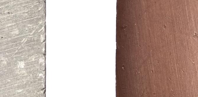
The Power of TiAlN Coating
The coating on an end mill is just as important as its geometry. TiAlN stands for Titanium Aluminum Nitride. It’s a thin, hard layer applied to the surface of the cutting tool that offers significant benefits, especially when machining abrasive or heat-generating materials like fiberglass composites:
- Exceptional Hardness: TiAlN is extremely hard, which dramatically increases the wear resistance of the end mill. This means the cutting edge stays sharp for much longer, allowing you to complete more parts without needing to change tools.
- High Heat Resistance: When machining, friction generates heat. TiAlN coatings are designed to withstand very high temperatures without breaking down. This prevents the coating itself from degrading and, crucially, helps to keep the cutting edge cooler.
- Reduced Friction: The smooth, dense surface of the TiAlN coating reduces friction between the tool and the workpiece material. Less friction means less heat generated and less material buildup on the cutting edge.
- Oxidation Layer Formation: At higher temperatures encountered during cutting, TiAlN forms a protective aluminum oxide layer. This layer further shields the tool and reduces the affinity of the workpiece material (like resin) to stick to the cutter.
For fiberglass, the heat resistance and reduced friction provided by TiAlN are critical. They help prevent the resin from softening and gumming up the flutes, which is a common problem with uncoated tools. This protection leads to a cleaner cut, less risk of melting, and a significantly longer tool life. You can find more about coatings and their applications on the Machinery Parts website, a reputable source for tooling information.
Key Features of the TiAlN 40-Degree Ball Nose End Mill
When selecting this tool, consider these essential features:
- Material: High-Speed Steel (HSS) or Carbide. Carbide is generally preferred for its rigidity and higher cutting speeds, especially with abrasive materials.
- Number of Flutes: For 3D surfacing in composites, 2 or 3 flutes are common. More flutes can provide a smoother finish but can be more prone to chip packing if not managed well. 2-flute designs often allow for better chip evacuation.
- Coating: TiAlN (Titanium Aluminum Nitride).
- Geometry: Ball Nose tip.
- Helix Angle: 40 Degrees.
- Diameter: This will depend on the scale and detail of your project. Smaller diameters (e.g., 1/8″, 1/4″, 6mm, 8mm) are common for detailed surfacing.
- Length of Cut: Ensure the length of cut is sufficient for the depth of your surfacing operations.
When to Use This Specialized End Mill
This specific end mill is ideal for a range of fiberglass applications, including:
- 3D Profiling and Contouring: Creating complex, sculpted shapes and artistic designs.
- Mold Making: Machining patterns or cavities in fiberglass molds.
- Prototyping: Quickly iterating on fiberglass part designs.
- Surface Finishing: Achieving a smooth, ready-to-paint or finish surface.
- Engraving: For detailed work where a rounded profile is desired.
Think of it as your go-to tool whenever you need to achieve smooth, flowing surfaces on fiberglass where standard milling cutters would struggle.
Setting Up for Success: CNC Parameters
Achieving excellent results with your TiAlN 40-degree ball nose end mill requires proper setup. Here are some general guidelines. Always start with conservative settings and increase gradually based on your machine’s rigidity, workpiece holding, and the specific fiberglass material you are using.
Recommended Cutting Parameters (General Guidelines)
These are starting points. Always consult the tool manufacturer’s recommendations and perform test cuts.
| Fiberglass Type | Spindle Speed (RPM) | Feed Rate (IPM or mm/min) | Depth of Cut (DOC) | Stepover (Tool Diameter %) |
|---|---|---|---|---|
| Standard Fiberglass (e.g., Woven Cloth) | 8,000 – 15,000 | 20 – 60 (IPM) / 500 – 1500 (mm/min) | 0.020″ – 0.060″ / 0.5mm – 1.5mm | 20% – 40% |
| Epoxy Resin Rich Composites | 10,000 – 18,000 | 25 – 70 (IPM) / 600 – 1800 (mm/min) | 0.015″ – 0.050″ / 0.4mm – 1.2mm | 15% – 30% |
| Gelcoat Surfaces | 12,000 – 20,000 | 15 – 50 (IPM) / 400 – 1200 (mm/min) | 0.010″ – 0.030″ / 0.25mm – 0.75mm | 10% – 25% |
Important Considerations for Machine Settings:
- Spindle Speed (RPM): This is how fast the tool spins. Higher speeds can generate more heat but can also lead to smoother cuts if the feed rate is matched correctly. Fiberglass tends to benefit from moderate to high speeds.
- Feed Rate: This is how fast the tool moves through the material. A slower feed rate might be needed for delicate finishes or to reduce chip load, but too slow can cause melting. A faster feed rate removes material quicker but requires sufficient chip clearance.
- Depth of Cut (DOC): This is how deep the tool cuts in a single pass. For surfacing, shallow depths are typically used to ensure a smooth finish and reduce stress on the tool.
- Stepover: This is the distance the tool moves sideways between passes. For 3D surfacing, a smaller stepover (e.g., 10-40% of the tool diameter) creates more overlapping passes, resulting in a smoother final surface. For a polished finish, you might use a very small stepover with multiple finishing passes.
- Coolant/Lubrication: While dry machining is possible with TiAlN, a light mist of coolant or a blast of compressed air can help manage heat and evacuate chips more effectively, especially in deeper cuts. Avoid flooding, as it can make chip removal harder.
- Workholding: Ensure your fiberglass part is securely clamped. Vibration can lead to poor finishes and tool breakage.
- Tool Engagement: For 3D surfacing, use Climb Milling whenever possible. This means the cutter engages the material on the “up” side of the rotation, which generally results in a cleaner cut and less tool pressure.
A good rule of thumb for new projects is to start with a conservative feed rate and depth of cut, then gradually increase them while listening to the machine and observing the chip formation. If you hear chatter or see excessive heat/smoke, reduce your feed rate or depth of cut.
Step-by-Step: Using Your TiAlN 40-Degree Ball Nose End Mill for Fiberglass Surfacing
Let’s walk through the process of using your specialized end mill. This assumes you have your CAD model designed and ready, and your CNC machine set up.
Step 1: Secure Your Workpiece
Properly clamp your fiberglass workpiece to your CNC machine’s bed. Use clamps, a vacuum table, or fixtures that will prevent any movement during the cutting process. Ensure the workholding doesn’t interfere with the planned toolpaths.
Step 2: Load the End Mill
Insert the TiAlN 40-degree ball nose end mill into your CNC machine’s spindle collet. Ensure it’s seated correctly and tightened securely. Double-check that the collet size matches the end mill shank for a precise fit.
Step 3: Set Your Zero and Tool Length Offset
Establish the work coordinate system (WCS) zero point on your workpiece. This is usually a corner or the center of your part. Next, set the tool length offset (TLO) for this specific end mill. This tells the machine the exact distance from the spindle face to the tip of the tool. This is critical for accurate depth control.
Step 4: Program Your Toolpaths
Use your CAM (Computer-Aided Manufacturing) software to generate the G-code for your surfacing operation. Key settings in your CAM software should include:
- Tool Selection: Choose your 40-degree ball nose end mill from the tool library.
- Tool Type: Ball Nose.
- Diameter: Enter the exact diameter of your end mill.
- Helix Angle: While your software might not directly input “40-degree helix,” it will select the appropriate tool profile.
- Coating: Note that the coating (TiAlN) is a material property and doesn’t directly affect CAM programming, but knowing it helps in setting parameters.
- Surface Area: Define the area to be surfaced.
- Cutting Strategy: Select a suitable 3D surfacing strategy (e.g., parallel, contour, radial). Parallel often gives the smoothest result for large areas.
- Stepover: Set a small percentage (e.g., 10-40%) for a fine finish.
- Stepdown (for a roughing pass if applicable): If you’re starting with a roughing pass, set a reasonable stepdown.
- Ramping/Plunging: Program gentle entry moves rather than a straight plunge cut. A slight ramp or helical entry is best.
- Climb vs. Conventional Milling: Prefer climb milling for composites.
If you are unsure about CAM software, resources from reputable educational institutions like Coursera offer introductory courses on CAM software, which can be incredibly helpful for beginners.
Step 5: Perform a Dry Run
Before cutting the actual material, run the program with the spindle off, but the machine moving. This allows you to visually inspect the toolpaths, check for any crashes against clamps or fixtures, and verify that the machine moves as expected. This step can save you from costly mistakes.
Step 6: Begin the Cut (with Caution)
Start the CNC machine. For this initial cut, consider using a slightly reduced feed rate and depth of cut. Listen to the sound of the cutting. A smooth, consistent hum is good. Any excessive chatter, squealing, or groaning indicates a problem that needs immediate attention.
Step 7: Monitor and Adjust
Watch the cutting process closely. Pay attention to:
- Chip Formation: Chips should be relatively fine and clear easily. Excessive dust or large shavings can indicate issues.
- Heat: While TiAlN helps, excessive heat can still be an issue. Look for any signs of smoking or melting resin around the cut. A light blast of air can help dissipate heat.
- Surface Finish: Periodically pause the job (if safe to do so) to inspect the surface finish.
If everything looks good, you can gradually increase the feed rate or depth of cut within the recommended parameters for better efficiency. However, for high-quality surfacing, prioritizing a smooth finish with conservative settings is often the best approach.
Step 8: Finishing Touches
Once the main surfacing operation is complete, you might want to perform a final “spring pass” or a very shallow finishing pass with a very small stepover (e.g., 5-10% of tool diameter) to achieve an ultra-smooth surface. This is where the ball nose shines again, blending the edges of each cutter path perfectly.
Maintenance and Best Practices
To get the most out of your investment in a specialized end mill, follow these maintenance tips:
- Clean After Use: After each session, clean the end mill to remove any dust, debris, or resin residue. A soft brush and some appropriate solvent (like denatured alcohol) can work well.
- Inspect for Wear: Regularly check the cutting edges for signs of dulling or chipping. A worn tool will degrade your finish and put more stress on your machine.
- Proper Storage: Store your end mills in a protective case or tool holder to prevent damage and keep them clean.
- Avoid Over