Need to clear cast iron with a 1/8-inch carbide end mill? Focus on chip evacuation! This guide shows proven ways to keep your small end mill cutting efficiently and avoid overheating, ensuring clean cuts in tough cast iron.
Welcome to Lathe Hub! Today, we’re tackling a common challenge for those of you venturing into milling cast iron with smaller tools: getting those pesky chips out of the way. Using a 1/8-inch carbide end mill on cast iron can feel like threading a needle with a toothpick, especially when chip evacuation becomes a real headache. It’s easy to overheat, break the tool, or end up with a messy surface finish if chips aren’t cleared properly. But don’t worry! With the right techniques, even a small end mill can tackle cast iron successfully. We’ll walk through everything you need to know, step-by-step, to ensure smooth, efficient machining and great results. Let’s dive in and make chip evacuation a breeze!
Why Chip Evacuation Matters for Small End Mills in Cast Iron
When you’re working with cast iron, a material known for its hardness and tendency to produce abrasive chips, clearing those chips away from the cutting zone is absolutely critical. This is especially true when using a small tool like a 1/8-inch carbide end mill. Imagine trying to cut through something tough, and the scraps just pile up and get in the way. That’s exactly what happens in miniature if chips aren’t removed.
These piled-up chips can:
Cause Recutting: Loose chips get pushed back into the cut by the flutes of the end mill. This isn’t just inefficient; it’s like trying to cut with a dull tool, generating excessive heat and stress.
Build Up Heat: Chips act as an insulator. When they cling to the end mill and the workpiece, they trap heat. For delicate carbide tools and the relatively low coolant flow you might get with a 1/8-inch end mill, this can quickly lead to thermal shock and tool failure.
Lead to Tool Breakage: Overheating, excessive force from recutting chips, and poor chip flow all increase the stress on the tiny cutting edges of your 1/8-inch end mill. This is a prime recipe for snapping the tool.
Create Poor Surface Finish: If chips aren’t removed, they can get trapped between the tool and the workpiece, leading to gouges and a rough, unacceptable surface finish on your cast iron.
Damage the Workpiece: Entrapped chips can dig into the softer cast iron, leaving marks or even damaging delicate features you’ve already machined.
For a small diameter tool like a 1/8-inch end mill, the flutes are relatively small, meaning they have less volume to carry chips away compared to larger tools. Cast iron chips are often relatively fine but can be sticky or abrasive. When you combine these factors, effective chip evacuation isn’t just a good idea – it’s essential for success.
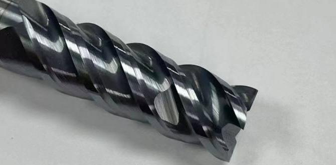
Understanding Your 1/8-Inch Carbide End Mill for Cast Iron
Before we get into the cutting strategies, let’s briefly appreciate the tool itself. A 1/8-inch carbide end mill is a precision instrument. Carbide, compared to High-Speed Steel (HSS), is much harder and can withstand higher cutting temperatures, making it ideal for materials like cast iron. However, carbide is also more brittle. This means impact and rapid temperature changes are its enemies.
When selecting a 1/8-inch end mill for cast iron, consider these features:
Number of Flutes: For cast iron, especially with small tools where chip evacuation is key, you generally want fewer flutes to maximize chip room.
2-Flute End Mills: These are often the best choice for cast iron. They offer larger flute gullets (the space between the cutting edges) to accommodate chips, and they are excellent for plunging and side milling.
3-Flute End Mills: Can be used, but they have smaller chip pockets. You’ll need to be more aggressive with your cutting parameters or use different strategies to manage chips.
4-Flute End Mills: Generally not recommended for cast iron with small tools like a 1/8-inch. Their chip pockets are very small, making effective evacuation extremely difficult.
Coating: Certain coatings can improve performance in cast iron by reducing friction and increasing heat resistance. While not always necessary for hobbyist use, coatings like TiAlN (Titanium Aluminum Nitride) or AlCrN (Aluminum Chromium Nitride) can offer benefits.
Geometry: Look for end mills designed for general machining or specifically for cast iron. These might have specific edge preparations or helix angles optimized for the material. A stub length can also be beneficial as it’s more rigid.
Shank: A 1/4-inch shank is common for 1/8-inch diameter end mills. Ensure your collet and tool holder can securely grip this shank.
For our purpose of proven cast iron evacuation with a 1/8-inch end mill, a 2-flute, solid carbide end mill, preferably of a stub length for rigidity, is your go-to tool.
Key Strategies for Proven Cast Iron Evacuation
Now, let’s get to the heart of it. How do we keep those chips from becoming a problem? It’s a combination of the right cutting parameters, the appropriate equipment, and specific machining techniques.
1. Cutting Parameters – The Foundation
Getting your speed and feed right is your first line of defense. For cast iron, you generally want to run carbide tools at their optimal speeds to keep the cutting edge engaged efficiently, but you need to manage chip load.
Surface Speed (SFM): Carbide tools can handle high surface speeds. For cast iron, a good starting point for a 1/8-inch carbide end mill might be anywhere from 200 to 400 SFM (Surface Feet per Minute). This is a wide range, and you’ll need to experiment.
Spindle Speed (RPM): Calculate this using the formula:
`RPM = (SFM 3.82) / Diameter`
For a 1/8-inch (0.125-inch) diameter tool and a target of 300 SFM:
`RPM = (300 3.82) / 0.125 = 9168 RPM`
So, around 9000-10000 RPM is a reasonable starting point.
Chip Load per Tooth (IPT): This is crucial for evacuation. It’s the thickness of the chip each cutting edge removes. For a 1/8-inch carbide end mill in cast iron, start with a very small chip load, often in the range of 0.0005 to 0.0015 inches per tooth (IPT).
Chip Load = (Feed Rate) / (RPM Number of Flutes)
Feed Rate (IPM): Calculate this based on your chip load:
`Feed Rate = RPM Number of Flutes Chip Load`
Using our example:
With 0.0005 IPT and a 2-flute mill at 9000 RPM: `Feed Rate = 9000 2 0.0005 = 9 IPM`
With 0.001 IPT and a 2-flute mill at 9000 RPM: `Feed Rate = 9000 2 0.001 = 18 IPM`
Start on the lower end and increase if the machine sounds happy and chips are forming well.
Why these parameters?
Lower chip loads mean shallower cuts, which produce thinner chips that are easier to evacuate. The higher RPMs help achieve that desired chip load at a manageable feed rate. Always consult your end mill manufacturer’s recommendations if available, as they often provide specific cutting data.
2. Machining Strategies – How You Cut
The way you engage the material makes a huge difference.
Climb Milling (Conventional Milling): In climb milling, the cutter rotates in the same direction as the feed. This results in a thin chip at the start of the cut, getting thicker as the flute exits. This is generally preferred for chip evacuation, as the chip is pushed away from the cutter. For cast iron and small end mills, climb milling is often the best choice.
Conventional Milling (Up Milling): Here, the cutter rotates against the feed direction. The chip starts thick and gets thinner. This can dig into the material and is more prone to creating backlash issues. It generally creates more heat and is less effective for chip evacuation in this scenario.
Stepover (for Pocketing/Profiling Sides): When milling a pocket or profiling a larger area, you’ll be taking multiple passes.
Small Stepover: For effective chip evacuation and to manage cutting forces, take smaller stepovers (the distance the tool moves sideways per pass). A stepover of 20-30% of the tool diameter is a good starting point (e.g., 0.024″ to 0.036″ for a 1/8″ mill). This keeps the radial depth of cut low.
Axial Depth of Cut: How deep you cut into the material vertically. This should be adjusted based on your tool’s capabilities and the rigidity of your setup. For a 1/8-inch end mill, you might start with an axial depth of cut around 0.1 times the tool diameter or less (around 0.01″ to 0.015″).
Slotting: When milling a slot whose width matches your end mill diameter (a full-width slot), chip evacuation becomes extremely difficult because there’s no room for chips to escape sideways. You’ll need to take shallow depths of cut and potentially use pecking cycles.
3. Lubrication and Coolant – Keeping Things Cool and Slipping
Cast iron generates heat quickly, and its abrasive nature can dull tools. Proper lubrication is essential.
Flood Coolant: If your mill has a flood coolant system, use it! The coolant will flush chips away, keep the cutting zone cool, and lubricate the cut. Aim for a high-pressure, high-volume flow directed right at the cutting point.
Mist Coolant/Air Blast: For machines without flood coolant, a mist coolant system or a powerful air blast is your next best option. The air blast is particularly effective for blowing chips out of the flutes and away from the cut. A mist coolant will also provide some cooling and lubrication.
Cutting Fluid/Lube Sticks: In simpler setups, applying a good quality cutting fluid or even a wax-based lube stick to the cutting edge can help. This reduces friction and can aid chip flow. Be mindful that this is less effective than a strong coolant flow for managing heat and chip evacuation in cast iron.
Peck Drilling/Pecking Cycles: If you’re slotting or plunging deep into the material, use a peck cycle. This involves plunging a short distance, retracting to clear chips, and repeating.
Standard Peck: Plunge a set depth, retract fully.
Chip Breaker Peck: Plunge, then retract slightly to break the chip.
A common peck depth might be 0.050″ to 0.100″ for a 1/8″ end mill.
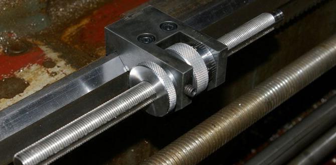
4. Rigidity and Setup – A Rock-Solid Foundation
This is non-negotiable when working with small, brittle tools.
Tool Holder: Use a high-quality collet chuck or ER collet chuck. Minimal runout (wobble) is critical. A worn-out or cheap collet can cause the end mill to vibrate, leading to poor finish and premature tool failure. Ensure the collet is clean and grips the shank firmly.
Shank Length: As mentioned, a stub-length end mill has a shorter, thicker shank relative to its diameter, making it much more rigid. If you have to extend the shank significantly from the collet, you introduce vibration and deflection. Keep the tool stick-out (how much of the tool is exposed beyond the collet) to the absolute minimum required for your cut.
Workholding: Your workpiece must be held incredibly securely. Any movement will lead to chatter, poor chip formation, and broken tools. Use appropriate clamps, vices, or fixtures, ensuring they don’t interfere with chip escape routes.
Machine Rigidity: Ensure your milling machine is robust and not prone to vibration. Even a small hobby mill can do this work if used carefully, but excessive play in the machine’s axes will exacerbate chip management issues.
Step-by-Step Guide: Milling a Small Pocket in Cast Iron
Let’s walk through a practical example: milling a small 1/2″ x 1/2″ pocket, 0.100″ deep, in a block of mild cast iron using a 1/8-inch 2-flute carbide end mill.
Tools and Materials
1/8-inch 2-flute solid carbide end mill (stub length recommended)
Mill (capable of at least 9000 RPM)
Collet or collet chuck for 1/8-inch shank
Secure workholding (vise, clamps)
Cast iron workpiece
Cutting fluid or mist/air coolant system
Safety glasses and appropriate PPE
Optional: Dial indicator to check tramming and runout
The Process
1. Prepare the Workpiece:
Clean the cast iron block thoroughly.
Use your digital calipers or a scriber to mark the center of your pocket.
Securely mount the workpiece in your milling vise or to the machine table. Ensure it’s flat and stable. If using a vise, ensure the jaws are clean and provide a firm grip without marring the surface too much.
2. Set Up the Machine:
Install the 1/8-inch collet into your collet chuck (or directly into the spindle if it’s a R8 or similar with a collet adapter).
Securely insert the 1/8-inch end mill into the collet, ensuring it’s gripped firmly.
Minimize Tool Stick-out: Adjust the end mill so only the cutting length needed for the 0.100″ depth is exposed. The less overhang, the more rigid and accurate your cut.
3. Tram the Spindle (If Necessary):
Ensure your spindle is trammed square to the table. This means the end mill should run perfectly parallel to the Z-axis and perpendicular to the X/Y axes. An out-of-tram spindle will cause uneven cutting and vibration. You can use a dial indicator for this.
4. Set the Zero Point:
Carefully bring the end mill down to the surface of the workpiece.
Use an edge finder or probe, or manually (with great care!) touch off the side and top of your workpiece to set your X, Y, and Z zero points in your machine controller or on its DRO (Digital Readout). For Z zero, you’ll typically touch off the top surface of the workpiece to define Z=0. The pocket depth of 0.100″ will be a negative Z movement.
5. Program or Manually Set Cutting Parameters & Strategy:
Spindle Speed (RPM): Set to ~9000-10000 RPM.
Feed Rate (IPM): Set to ~10-18 IPM (based on ~0.0005-0.001″ chip load and 2 flutes).
Stepover (for clearing pocket): We’ll mill a 0.500″ pocket with a 0.125″ end mill. This is called “full width slotting” or trying to mill a slot wider than the tool’s actual capability for clearance. To mill a 0.500″ pocket, you cannot use a full 0.125″ stepover. You’ll need multiple passes.
Strategy: Use a stepover of about 50-60% of the tool diameter (approx 0.060″ – 0.075″). This allows a bit more chip room than a very small stepover, but still requires careful chip management. You’ll need slightly more than 4 passes to clear the 0.500″ width.
Depth of Cut (Axial): Set to a shallow depth, e.g., 0.050″ per pass. This reduces the load on the tool and makes chip evacuation easier.
Milling Direction: Use Climb Milling.
Coolant: Turn on your mist or air blast.
6. Begin the Cut (First Pass):
Start the spindle.
Initiate the feed rate.
Move the end mill to the starting point for your pocket. Perform a shallow plunge (e.g., 0.020″) to enter the material. Do not plunge at the full feed rate except in cases of peck drilling. For a side milling “entry,” you might want to ramp into the material very gently. For a pocket, it’s often best to enter the material from the side at the full depth of the first cut, or use a short ramp.
Engage Climb Milling: Carefully feed the end mill into the material. For a pocket, after the initial entry (plunge or ramp), you’ll feed sideways, then engage the vertical feed (Z-axis) to reach your first depth (0.050″).
Observe: Watch the chips. Are they being flung away? Are they accumulating? Is the sound of the cut smooth? Listen for any signs of distress.
**