Building your own wood lathe spindle lock tool is a smart move for any woodturner. This simple, DIY project ensures you can securely lock your lathe’s spindle, making for safer and more efficient work. It’s an essential accessory that keeps your projects from moving unexpectedly.
Wood Lathe Spindle Lock Tool DIY: Proven Essential

Hey there, fellow woodturners! Daniel Bates here from Lathe Hub. Ever been in the middle of a delicate turning project, only to have your workpiece shift slightly when you didn’t want it to? It’s a common frustration, and a potentially dangerous one. That’s where a good spindle lock tool comes in. While you can buy them, building one yourself is surprisingly straightforward and a fantastic beginner project. It gives you a hands-on understanding of how this vital piece of workshop equipment works, and the satisfaction of having made it yourself. Today, we’re going to dive into creating your very own, proven essential wood lathe spindle lock tool.
Why You Need a Spindle Lock Tool

Before we get our hands dirty, let’s talk about why this tool is so important. A spindle lock, also known as a spindle stop or spindle brake, is designed to prevent the lathe’s spindle from rotating. You might be thinking, “Why would I want to stop it from spinning? That’s the whole point of a lathe!” Well, there are several key situations where a locked spindle is not just helpful, but absolutely crucial for both safety and precision.
The most common need is for changing accessories. When you need to swap out a chuck for a faceplate, mount a jam chuck, or simply remove a workpiece that’s stubbornly stuck, the spindle must be held stationary. Without a lock, any force you apply to loosen a screw or a jam nut will just cause the whole thing – spindling, chuck, and workpiece – to spin around with you. This is not only ineffective but can also lead to scraped knuckles, damaged threads, or even a dropped workpiece.
Another critical use is for tasks that require precise alignment or drilling operations. If you’re drilling a hole precisely in the center of a tenon or mortise, you need the workpiece to stay put. Similarly, when parting off stock, having the spindle locked can give you better control and a cleaner cut. For those undertaking more advanced projects like creating segmented bowls or intricate inlays, the ability to lock the spindle and accurately re-align a workpiece is paramount.
Finally, it’s a crucial safety feature. In an emergency, or even just when you’re working with particularly stubborn fittings, a spindle lock can provide a firm, reliable way to halt the momentum of the rotating headstock. This gives you peace of mind and a direct line of action to stop motion when needed.
Understanding the Basic Design
The beauty of a wood lathe spindle lock tool is its simplicity. At its core, it’s a lever mechanism that engages with a part of the headstock to physically stop the spindle from turning. Most are designed to interact with the drive or pulley shaft, or sometimes directly with notches or holes that might be present on the spindle or faceplate.
The common elements you’ll find in most spindle lock designs are:
A Handle/Lever: This is what you’ll grip and turn to apply pressure.
A Cam or Wedge: This shaped part is what actually makes contact to lock the spindle. It’s designed to tighten its grip as you turn.
A Mounting Point: This piece attaches to the lathe’s headstock, providing a stable base for the cam and handle.
The goal of our DIY project is to replicate these fundamental functions using readily available materials and common workshop tools.
Materials You’ll Need for Your DIY Spindle Lock Tool

For this project, we’ll focus on a robust and very common DIY spindle lock design that uses a piece of round stock and a shaped cam. This is effective and relatively easy to fabricate.
Here’s a list of the materials you’ll want to gather:
Steel Round Stock: Approximately 1″ (25mm) to 1.5″ (38mm) in diameter and about 6″ (150mm) to 8″ (200mm) long. This will form the main body of your tool. Mild steel is perfectly adequate here.
Steel Flat Bar: A piece about 1/4″ (6mm) to 3/8″ (10mm) thick, 1″ (25mm) to 1.5″ (38mm) wide, and about 8″ (200mm) to 10″ (250mm) long. This will be shaped into the cam.
Steel Rod or Bolt: About 1/2″ (12mm) diameter and 4″ (100mm) long. This will act as the pivot pin for your cam.
Handle Material: This could be a piece of sturdy round wood (like hardwood dowel, about 1″ diameter and 6″ long), a metal tube, or even a pre-made steel handle.
Fasteners: Depending on your design, you might need bolts, nuts, and washers. For the pivot pin, you’ll likely need a couple of nuts and possibly some washers to secure it.
Optional: Weldable Metal: If you have access to a welder, this can simplify some assembly steps considerably.
Tooling Considerations:
For this project, you’ll ideally have access to a metalworking setup. Basic tools would include:
Hacksaw or Bandsaw: For cutting steel.
Drill Press or Hand Drill: With metal drill bits.
Hammer: For shaping and persuasion.
Files: For deburring and shaping edges.
Vise: Essential for holding parts securely.
Grinder (Angle Grinder or Bench Grinder): For shaping and smoothing metal.
Optional: Welder: For stronger, more integrated assembly.
Measuring Tools: Tape measure, ruler, caliper.
Marking Tools: Scribe, chalk, or permanent marker.
It’s important to note that while you can improvise with some steps, having access to a drill press and a grinder will significantly improve the accuracy, strength, and overall quality of your finished spindle lock.
Step-by-Step Guide to Building Your Spindle Lock Tool

This guide outlines a common and effective method for creating a cam-style spindle lock. We’ll be focusing on a design that clamps onto the spindle pulley or a wheel.
Step 1: Prepare the Main Body
1. Cut the Round Stock: Using your hacksaw or bandsaw, cut the steel round stock to your desired length (e.g., 6-8 inches). Ensure the cut is as square as possible.
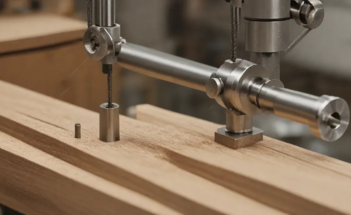
2. Drill the Pivot Hole: This is a critical step. Decide where you want your cam to pivot. A good starting point is about 1″ to 1.5″ from one end of the round stock. Mark the center accurately.
Using your drill press (preferred for accuracy) or hand drill, drill a hole through the center of the round stock. This hole should be sized to fit your chosen pivot rod or bolt (e.g., 1/2″ or 12mm).
Tip: Use a center punch to create a dimple before drilling; this prevents the drill bit from wandering. Lubricate the drill bit with cutting oil for a cleaner hole and to prolong its life.
3. Machine the Engaging Surface (Optional but Recommended): If you have a lathe or milling machine available, you can greatly improve the tool’s performance.
On a Lathe: Mount the round stock in your chuck. Face off the end that will engage the pulley. Then, carefully turn down a section of the round stock, creating a semi-circular or slightly tapered “jaw” that will press against the pulley. Aim for a smooth, semi-circular profile that will grip without damaging the pulley.
On a Mill: Use a milling vise to hold the round stock. Mill a semi-circular or flat-bottomed notch into the side of the round stock, ensuring it’s perfectly centered. This notch is what will dig into the pulley to hold it.
Without a Lathe/Mill: You can achieve a decent grip using a grinder. Carefully grind a concave shape or a flat ledge onto the side of the round stock. Take your time to make it as symmetrical as possible.
Step 2: Fabricate the Cam
1. Cut the Flat Bar: Cut a piece of the steel flat bar to a suitable length (e.g., 8-10 inches).
2. Shape the Cam Profile: This is the most important part of the cam. One end of the flat bar needs to be shaped into a camming surface that, when rotated, will push firmly against your workpiece or the pulley.
The idea is to have a curve that starts with a wider radius and tapers to a narrower one. As you rotate the cam, this taper forces it against the opposing surface.
Using a Grinder: This is a common method. Mark out your desired cam profile on the end of the flat bar. Gradually grind away the material, creating a smooth, sweeping curve. You want a shape that will engage securely and apply consistent pressure. Aim for a shape that is roughly a quarter-circle or an eccentric curve.
On a Lathe/Mill: If you can, mount the flat bar and turn or mill an eccentric profile onto the end. This will yield a more precise and effective cam.
Step 3: Assemble the Tool
1. Position the Cam: Place your shaped cam onto the steel round stock, aligning the pivot hole you drilled in Step 1 with the desired pivot point of the cam mechanism. The cam should be able to swing freely.
2. Attach the Pivot Pin: Insert your steel rod or bolt through the hole in the round stock and the corresponding hole in the cam.
If using a rod: You may need to drill a clearance hole in the cam. Secure the rod by peening (hammering) over the ends, or by using two nuts on either side of the cam to lock it in place. Ensure the cam can still pivot smoothly.
If using a bolt: Insert the bolt and secure it with a nut. Use a few washers if needed to allow free movement. A locking nut (nyloc) is a good idea here to prevent it from loosening over time.
3. Add the Handle:
For a round stock body: If you’re using a solid round stock body, you can drill and tap a hole on the opposite end of the pivot point to accept a bolt, onto which you’ll thread your handle material (wooden dowel, metal tube, or a dedicated handle).
Alternatively (and often stronger): If you’re using a welder, you can weld a boss or a threaded insert onto the main round stock body where you want your handle.
Another simple method: Drill a hole through the round stock body, perpendicular to the pivot pin hole, and insert a sturdy bolt. The handle can then be threaded onto this bolt, or a piece of pipe slipped over it and secured with set screws.
Wooden Handle: For a wooden handle, drill a hole into the end of your hardwood dowel slightly smaller than your chosen bolt. Drive the bolt into the dowel, or thread it. Then, thread this bolt into the handle attachment point on the main body.
Step 4: Refine and Test
1. Smooth Edges: Use a file and sandpaper to smooth any sharp edges or burrs on your completed tool. This makes it safer to handle and prevents scratching your lathe.
2. Test the Action: Mount your tool onto your lathe’s headstock. Position the cam against the spindle pulley or a wheel. Gently turn the handle. You should feel the cam engaging and tightening, bringing the spindle to a halt.
3. Adjust if Necessary: If the tool doesn’t grip firmly, you may need to adjust the cam profile or the pivot point. If it’s too stiff, check for binding and smooth the pivot.
4. Consider Mounting (Optional): Some DIY spindle locks are designed to be held by hand. Others might benefit from a simple bracket that attaches to the lathe bed or headstock casting, allowing the tool to swing out of the way when not in use. This is more advanced but can be a nice addition.
Tips for a Better Spindle Lock
Material Choice: While mild steel is adequate, using a harder steel for the camming surface will provide greater durability and resistance to wear, especially if you use it frequently.
Ergonomics: Make sure the handle is comfortable to grip and provides enough leverage. A longer handle increases leverage but can sometimes make precise control trickier.
Cam Profile is Key: The shape of the cam is paramount. It needs to be smooth enough to engage without damaging surfaces, but steep enough to provide a solid lock. Test the profile on a spare piece of metal or wood until you’re happy with its grip.
Lubrication: A little grease on the pivot point will ensure smooth operation and prevent premature wear.
Alternative DIY Spindle Lock Designs
While the cam-style lock is very popular, there are other DIY approaches you can consider, depending on your lathe’s design and your available materials.
The Pin-Style Spindle Lock
Some lathes have pinholes or notches specifically designed for locking the spindle. If your lathe has these features (often on the faceplate or a drive pulley), a simple pin-style lock can be extremely effective.
How it works: A sturdy pin (often a bolt with its head cut off and a handle attached, or a custom-machined pin) is inserted through the headstock casting and into the corresponding hole or notch on the rotating part.
DIY Approach:
1. Identify the locking hole/notch on your lathe.
2. Fabricate a pin that fits snugly. This could be a bolt, a piece of hardened steel rod, or even a strong dowel for very light-duty use (not recommended for significant force).
3. Add a handle (e.g., a T-handle, a bend in the bolt, or a simple grip) to make it easy to insert and remove.
Pros: Very simple, very secure if the lathe is designed for it, quick to engage/disengage.
Cons: Only works if your lathe has specific locking points.
The Wrap-Around Type Spindle Lock
This is a more generalized design that can work on many lathes, particularly those with a prominent pulley or drive shaft.
How it works: This design essentially creates a strong clamp that wraps around the pulley or shaft. Turning a knob or lever tightens the clamp, preventing rotation.
DIY Approach:
1. This often involves fabricating metal jaws that can open and close.
2. A central threaded rod or bolt with a handle is used to tighten the jaws around the spindle pulley.
3. The internal surfaces of the jaws might be lined with rubber or a non-marring material for better grip and to protect the pulley.
Pros: Can be adaptable to various lathes, provides good gripping surface.
Cons: Can be more complex to fabricate accurately, requires careful alignment.
Spindle Lock for Specific Lathes
It’s also worth noting that some DIY spindle lock designs are highly specific to the make and model of the wood lathe. For example, some older lathes have specific spindle nose threads or pulley arrangements that lend themselves to custom-built solutions. Always consult your lathe’s manual or online forums for your specific model if you’re looking for ideas beyond the general designs. Resources like the American Association of Woodturners (AAW) can be invaluable for finding community-driven solutions and advice.
For our focus today, the cam-style lock remains a fantastic and achievable project for most beginners.
Safety First: Using Your Spindle Lock Correctly
A DIY tool is only as good as its user. While building your spindle lock is a rewarding process, using it safely is paramount.
Ensure a Solid Grip: When locking the spindle, ensure the cam is firmly seated against the pulley or shaft. You don’t want it slipping. Apply steady pressure.
Never Force It: If the spindle lock is difficult to engage, don’t force it. There might be a misalignment, or the cam profile might need adjustment. Forcing it can damage your lathe or the tool.
Disengage Before Starting: Always, always, always ensure your spindle lock is fully disengaged before turning on the lathe. Turning on the lathe with the spindle locked can cause catastrophic damage to the spindle, motor, and the lock tool itself, and could potentially throw pieces of metal. This is the single most important safety rule.
Check for Wear: Periodically inspect your DIY spindle lock for any signs of wear, especially on the camming surface and the pivot point. Worn parts can lead to a loss of grip or a failure to engage properly.
* Know Your Lathe: Familiarize yourself with your lathe’s headstock. Understand the parts that your spindle lock will engage with. Is it a smooth pulley, a grooved pulley, or a shaft with a flat? This knowledge will help you build a more effective and safer tool.
By following these simple safety guidelines, you can enjoy the benefits of your DIY spindle lock tool with confidence.
Integrating Your Spindle Lock into Specific Tasks
Let’s look at how your new DIY spindle lock will make common woodworking tasks significantly easier and safer.
Changing Lathe Accessories (Chucks, Faceplates)
This is the quintessential task for a spindle lock. When removing or installing a chuck or faceplate that’s been tightened onto the spindle, you need to stop the spindle from turning.
1. Engage Lock: Turn off the lathe. Once it has come to a complete stop, engage your DIY spindle lock firmly against the pulley or drive shaft.
